Last Updated on February 8, 2026 by Maged kamel
Definition of the effective area for tension members.
Effective area and shear lag factor.
To explain the concept of effective area, let us consider the shape shown in the sketch: an angle under a tension force P, with bolts at the lower leg.
The shaded area is stressed very little, so most of the stress is concentrated at the bolts on the lower leg. And connected to the plate.
As the load is applied, the load transfer to the unbolted portion does not occur immediately; instead, it lags. This phenomenon is called shear lag.
Note that the angle is connected to only one leg, and that leg is connected to the plate. This leads to a concentration of stress along that leg and leaves the unconnected leg unstressed or only slightly stressed.

This means that stress in the connected portion will increase due to the unconnected part’s lack of sharing, potentially exceeding the Fy. The further we move out from the connection, the more uniform the stress becomes.
The shear transfer has lagged in the transition region, a phenomenon known as shear lag.
This leads to an expression for the percentage of the effective area relative to the net area, called the U value. The U value depends on two factors. The first factor is the x̅ bar, which is the distance from the Cg to the connecting plate. factor. The second factor is the connection length L.
Effect of x̅ and connection length on the shear lag factor.
Comparing two shapes, shape a with an equal angle and shape b with an unequal angle, where the fasteners exist on the long leg side, the observation is that when the distance x̅ is smaller, the effectiveness of the connection improves. The smaller the value of x̅, the larger the effective areas of the member and, thus, the larger the member’s strength.
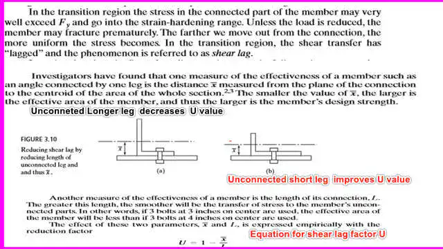
As the statistics show, x̅ is closer because the larger area has a closer CG. So the angle in shape b is more effective than in shape a. Shear lag affects both bolted and welded connections; the effective net area concept applies to both types, and for welded connections, Ae = U* An.
Does the shear lag factor U have a minimum value?
The U shear lag factor U has a minimum value specified by the AISC, which is the ratio of the connected area to the total area; this holds true for open areas. The Code identifies shapes under tension as opening shapes, such as W, M, S, HP C, and their related structural shapes and angles.
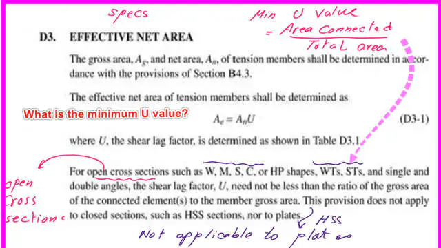
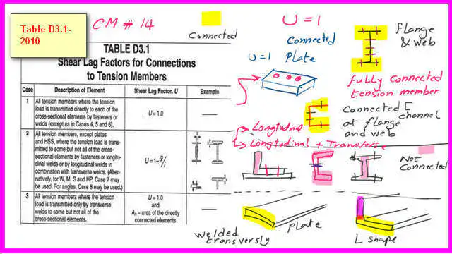
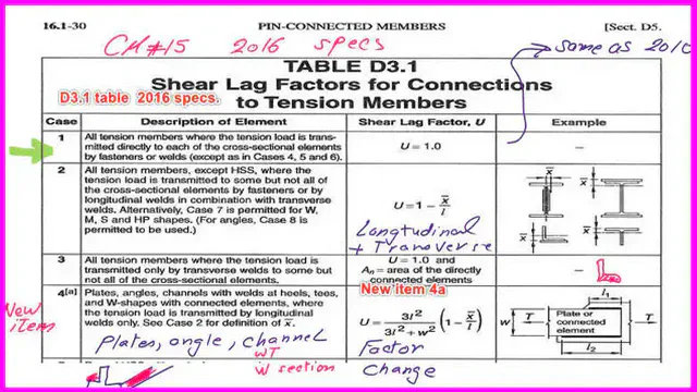
Table D3.1 shows the shear lag factor for CM-14 and its related specs.
Case-1 is the first case for which the U value equals 1; it involves the fully connected connection between two steel shapes. For instance, if we have two W shapes or two channels connected at flanges and webs or completely welded.
Case 2 is the second case in which the U value is less than 1, and we need to find the two parameters x̅ and L.
This case includes connecting two steel shapes that are not fully connected. For instance, two W shapes or two channels connected only at flanges, through webs, or partially welded.
Case 3 is the case where the two connected shapes are connected through transverse welds, for instance, two plates or two angles through one leg for each. The U value is equal to 1.
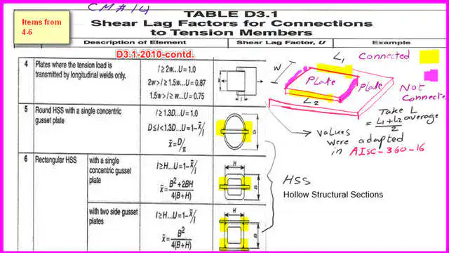
Case 4 is where the two connected plates are joined by two longitudinal welds. The U value depends on the width of the connection. There are three values of U based on the W/L ratio. The length of connection L is the average length of the two longitudinal lengths.
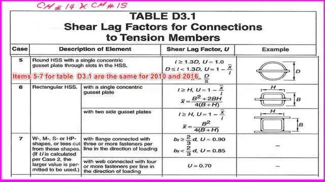
Case 5 is a round HSS with a single concentric plate, and case 6 is a rectangular HSS with a single concentric plate or two side gusset plates.
Shear lag factor as per CM#15 and related AISC-360-16.
The value of U for case 1 for table D3.1 as per CM#15 is the same as case 1 for table D3.1 as per CM#14
The major difference between Table D3.1 in AISC-360-16 and Table D3.1-AISC-360-2010 is between cases 2 and 4.
For CM#15, case 2 was revised to include connected members through longitudinal welds in combination with transverse welds.
For CM#15, case 4 was revised to case 4a, which includes plates, angles, Tees, W shapes, and channels through longitudinal welds only. The u equation has been revised.
Common values for U for cases 5-8 between CM#14 and CM#15.
For Cases 5-8 in Table D.31, the shear lag factors are the same for CM#14 and CM#15. Case 7 includes W,m, S, Hp, or shapes cut from W,m, and Tees.
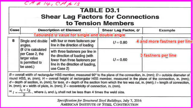
Case 8 is for a single or double angle connected with bolts; the value of u depends on whether the connection uses four or more bolts or three or fewer.
Solved example 4-1: How can we estimate the shear lag factor for a single angle?
It is required to determine the shear lag factor U, the net area An, and the effective area Ae. We have an angle measuring 5x5x3/8 inch, with 4 bolts connecting one plate to the other on one side.
We want to estimate the value of U. Bolts, which are four 3/4-inch A325 N bolts, so we can estimate the hole diameter by adding 1/8 inch to the bolt diameter.
The hole’s diameter is 7/8 inch. Our expression U=1- x̅/ L, where x̅ is the distance perpendicular to the load. Refer to the table. Then we get the gross area for the 5x5x3/8-inch angle, which is 3.65 in^2.
Check the CG distance. The C.G. is in the y-direction, but it is referenced as x̅ and equals 1.37 inches. What about the L distance? It is the distance between the first and last bolts, equal to (3*3=9 inches), so U=1-(1.37/9)=0.848.

This is the calculation for the U value, but according to the table, U = 0.80 for four or more fasteners, as in the third case shown.

We select the bigger of the two values, 0.848, and then estimate the net area using the usual equation: Anet=Ag-(n*dh*tl).
We can get the y bar for the angle L5xL5x 3/8 from Table 1-7. y bar. We can see that the y bar is parallel to the unconnected leg.
The net area Anet=Ag -Ag- sum(d*t), Ag =3.65 inch2, dia 7/8 and t=3/8 of the angle, sum(d*t)=7/8*3/8, only one bolt hole to be deducted, to be deducted from 3.65 inch2.
The value is 3.32 in^2; then A-effective = 0.848*3.32 = 2.82 in^2, which was the first example of the effective area.

This is a quick reference to posts that include practice problems for the U value.
A) Design strength for a given W section bolted at flanges; this is the topic of the next post; it is a direct application for cases 2 and 7 for shear lag factor. The next post-post 7- is A Solved problem for Design strength.
B) For the shear lag factor U value for a welded angle, which applies to case 2, please refer to post 8.
C) For a connected angle by bolts for one leg only, the value of U is governed by the maximum value between case 2 and case 8. Please refer to the first solved problem in post 9.
D) For a connected section by transverse weld only in case 3, please refer to the post-9A-Practice problem: transverse weld of a WT section.
E) For a connected section by longitudinal weld only in case 4, please refer to the post-9b-Practice problem-longitudinal weld of a plate section.
F) For a connected section by longitudinal weld only, case 4, please refer to the post-9C-Practice problem-longitudinal weld of a C section.
For the same angle welded, the value of U is governed by case 2; please refer to the second solved example in post 9.
The PDf file for this post can be viewed or downloaded from the following document.
For a more detailed illustration of block shear, there is a very useful external link to the Tension Members chapter 3. A Beginner’s Guide to the Steel Construction Manual, 14th ed.
Chapter 3 – Tension Members– A Beginner’s Guide to Structural Engineering is a great external resource.A Beginner’s Guide to the Steel Construction Manual, 15th ed.
A useful external link –Tensile yielding and tensile rupture. A Beginner’s Guide to the Steel Construction Manual, 16th ed.