Solved Problem For design strength of tension member.
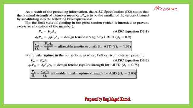
Limit states for tension members.
Limit state of yielding and rupture and the corresponding values for φt= 0.75 and Ωt=2.00 for each case.

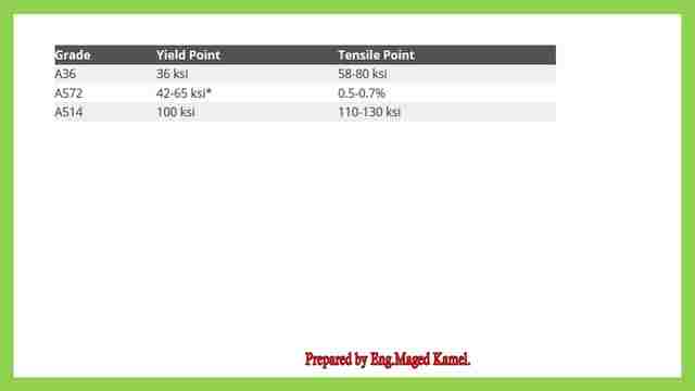
This table includes the various values for Fy and Fult, for ASTM A 36 and for ASTM A 572, the grade should be specified Fy= 42 ksi till 65 ksi, for ASTM A514 Fy= 100 ksi, Fy= 100 ksi.

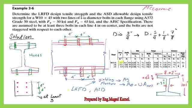
A Solved problem 3-6-tensile strength for W section-bolted at flanges.
Our solved problem 3-6, Determine the LRFD design tensile strength and the ASD allowable design tensile strength for a W10x45 with two lines of 3/4 inch in diameter bolts in each flange, using ASTM A572 grade 50, Fy=50 ksi and Fu=65 ksi and the Aisc specification.
Each line has 3 bolts for both the upper and lower flange, Our first step is to get the area of the w section, by using the relevant table For W10-45.
The area Ag=13.30 inch2, the diameter of each bolt is 3/4 inch, then we add 1/8 inch, the overall diameter will be 7/8 inch.
Back to the statement of this solved problem, the bolts are assumed to be at least three bolts, there is an item in the table that states At least three bolts and more, the U value can be obtained via the table.

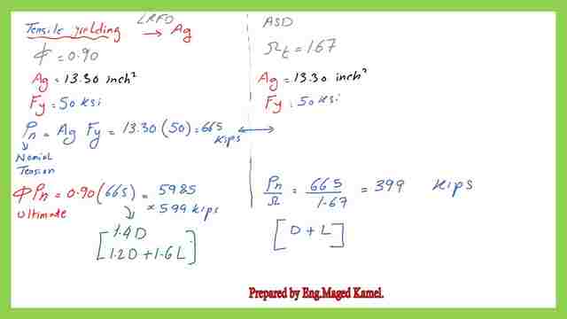
Design strength by yielding for W section-LRFD-ASD.
We can proceed to evaluate the LRFD for ASD tensile strength by Yielding as shown in the following picture, for the Solved problem 3-6. In that calculation, we need only the gross area of the given section.
For LRFD, Ag=3.30 inch2, Fy=50 ksi, φt =0.90, the φt *Pn=0.9*3.30*50=599 kips this is the LRFD Nominal strength for design based on yielding.
For ASD, Ag=3.30 inch2, Fult=50 ksi,1/ Ωt =1/1.67, the 1/ Ωt *Pn=(1/1.67)*3.30*50=399 kips this is the ASD Nominal strength for design based on yielding.

How to estimate the shear lag factor-U for the W section?
This is how we estimate U for W10x45 by converting to two WT 5×22.50, from which we can get the y bar value, which is 0.907, and consider it as the x bar in the equation of U=(1- x̅ /L). Use the equation U=(1- x̅ /L), and then substitute by x̅ =0.907, we get U=0.8867.This is Case 2 for the shear lag factor value.
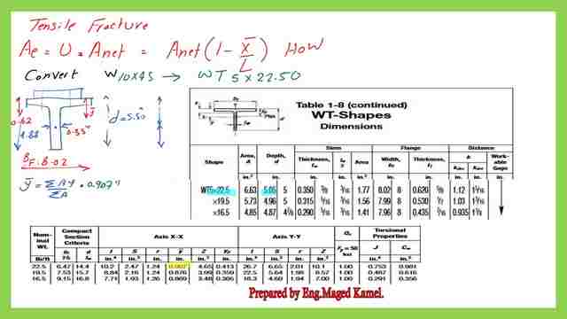

We can also Find the shear lag factor from case 7, for three fasteners or more.
While if we use the tables for 3 fasteners, with bf/d>2/3, we have U=0.90, which is bigger than the previous value of U and hence can be used.
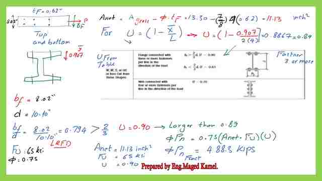

We have 4 bolts, 2 at the top flange and the other 2 at the lower flange, our dia of the bolt is 7/8 inch, and T flange=0.62″. We can estimate Ant=Agross-4*(7/8)*0.62=13.30-4*7/8*0.62 =11.13 inch2, Fult=65 ksi, as given in the solved problem.
After selecting the bigger value of U, which is equal to 0.90. We can get the value of the effective area.
For Aeff=Anet*U=11.13*0.90=10.02 inch2. Tensile rupture by LRFD can be estimated as φt*A eff*Fult=0.75*10.02*65=488.30 kips.
While for tensile rupture by the ASD, it can be estimated as 1/Ωt*A eff*U*Fult=(1/2)*10.02*65=325.65 kips.
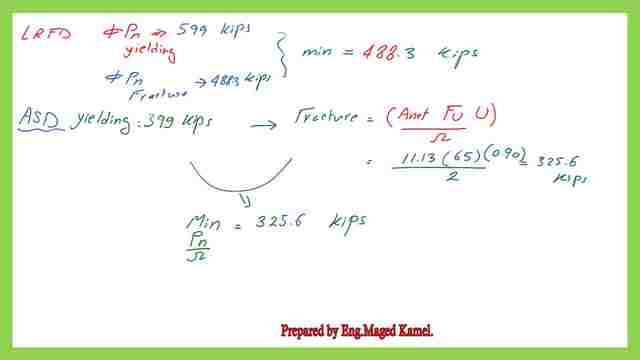
For the LRFD tensile strength, take the minimum value of the LRFD Limit states for yielding and rupture as follows:
φt*Pn=min of (599, 488.30)=488.30 kips.
While for the ASD tensile strength, take the minimum value of the ASD Limit states for yielding and rupture as follows: (Pn/Ωt)=min(399, 325.6)=325.60 kips.

This is the Pdf file used for the illustration of this post.
For the next post, A Solved problem 4-2 for shear Lag factor U.
Chapter 3 – Tension Members– A Beginner’s Guide to Structural Engineering is a great external resource.

