A Solved problem 4-2 for shear Lag factor U for a welded connection.
We continue together with the shear lag factor, how to evaluate it? We are going to have a look at the solved problem-4-2, from Abi Aghayre, from the structural steel design version-3, the solved problem concerns the weld, for one leg of an angle.
This is the Grade of steel and the corresponding Fy, Fult values for A36, fy=36 ksi, fult=58-80 ksi, A572 grade,fy=50 ksi, A572 grade, the value of tensile point=65 ksi


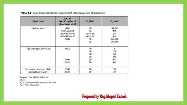

These are the tables as per the latest revision of AISC-360-16, which we are using for the estimation of the values of the shear lag factor, at the first table for plates, the three cases of the plates were explained.
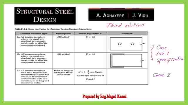

Case No. 3 is the case of any tension member that is welded to another element by a transverse weld, for which the U value=1.00.
Case No.4 in this case plate, angle, and C channel and angle that are welded in the longitudinal direction only tension to another element, for which the U value is given by an equation to estimate the U value.
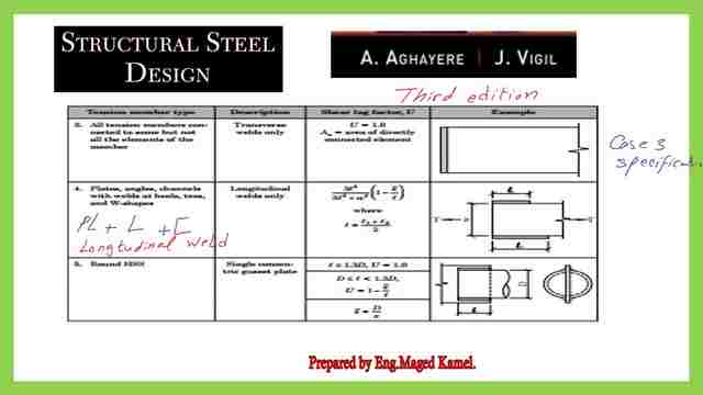

These are the various cases of rectangular connected to a single plate, or by two plates and the corresponding value for each case.
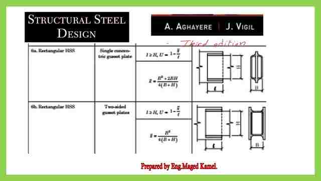

Shear lag table part -4- based on the latest specification adopted by Prof. Abi Aghayere’s book.
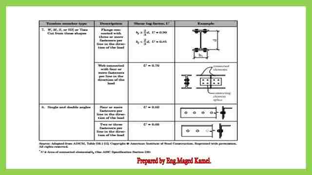

These are the other cases from 7 &8 and the corresponding U- value.
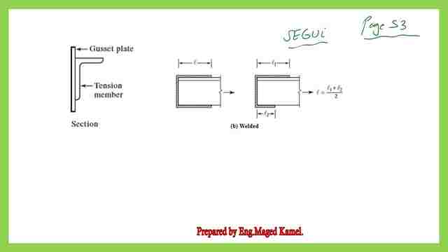
On page-53 from Prof. Segui’s book, if you have a Tension member, that is welded in one leg with a plate at the vertical direction as shown as well as welded at the longitudinal top and bottom edges for the other leg, whether has an equal weld distance for a both upper and lower portion or with a different top and bottom sides distances for which L1 is the weld length for the upper part of the leg with the plate and L 2 is the length of the weld for the lower portion of the leg.
The upper leg is not acting, it is only welded, but as before in the case of the bolt, this leg is not utilized in tension instead of multiplying the area net as in the case of bolts, this time by using welds, no deduction in the area and the A gross will be used in the calculation.
The value of tension fracture Pn=AeFult=AgU*Fult will be increased accordingly.

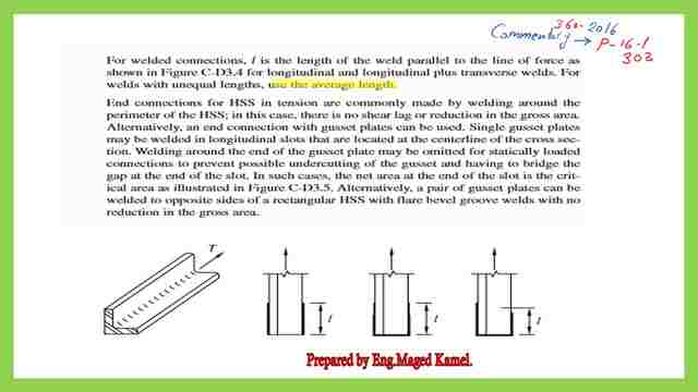
From commentary 16-1 page 303, for welded connection, L is the length of the weld parallel to the line of force, and here as shown the different lengths of weld in the direction of the force. In Fig CD-3.4 for longitudinal and longitudinal plus transverse welds, L is the length parallel to the force.
In the case of different lengths, use the average length, which is now our concern for the next solved problem 4-2 for shear lag.

The Solved problem 4-2 for shear Lag factor U for welded angle.
If we proceed to our solved problem 4-2 for shear lag, evaluate the U value for welded connection angle L 5x5x3/8 welded within three sides. We have the U value less than 1 since one leg is not connected. The lower weld length is 4″, the upper portion weld length is 6 “, and welded at the edge with length= angle height. the upper leg is not connected to the backplate.
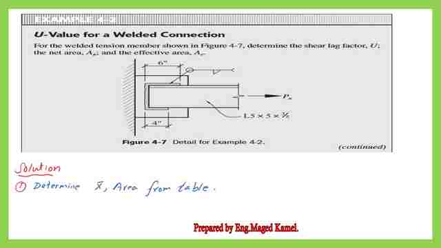

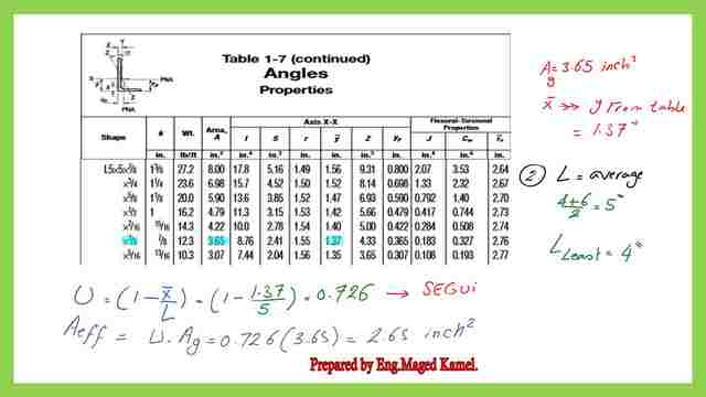
The steps to be followed, are first to determine the x̅, and the area of the angle. We have an angle of 5x5x3/8″, for which the area is =3.65 inch2. he x̅, which is y̅ value from the table=1.37″
x̅/L is taken L as the average length of the weld for the upper weld length =6″ and the length of the lower weld=4″.
L=0.50*(4+6)=5″. x̅/L=1.37/5=0.726 refereeing to Prof. Segui and code requirement.
Shear Lag factor U in more detail.
The shear value of U value =0.726. The effective area Ae which is=AgU=0.7263.65=2.65 inch2.

This is the PDF file used for the illustration of this post.
The next post is for Two Solved problems for the effective net area.
Chapter 3 – Tension Members– A Beginner’s Guide to Structural Engineering is a great external resource.

