Last Updated on February 20, 2026 by Maged kamel
Regions for Lateral-torsional buckling for beams-2/2
We have three regions for Lateral-torsional buckling for beams, with similar shapes to the previous zones at the local flange buckling and web for steel beams.
Still, instead of using the λ factor in the horizontal axis as λp plastic and λr elastic, we use Lp, plastic length, Lr, which is the unbraced length, which is a boundary between elastic and inelastic lateral-torsional buckling in Feet.
The first of the three Regions for Lateral-torsional starts from Lb=0, where Lb stands for bracing length, and goes to lb= Lp.
The Lp is the plastic length between bracings. The second point is Lr for the unbraced elastic moment, which has a stress equal to 0.7Fy*Sx, where Sx is the elastic section modulus, and the inclined line has a zone of inelastic buckling. While the last curved zone is for elastic buckling, every line has a reference equation.
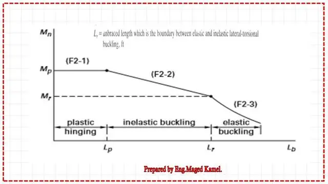
Each formula starts from F2-1 to F2-3. Our chapter is Chapter 3, Part 2, covering the three regions of Lateral-torsional buckling for beams, as shown in the next slide image with the relevant equation.
This is a reference from the AISC specifications for yielding structural steel beams.
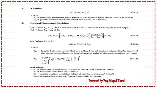
Cb-coefficient of bending.
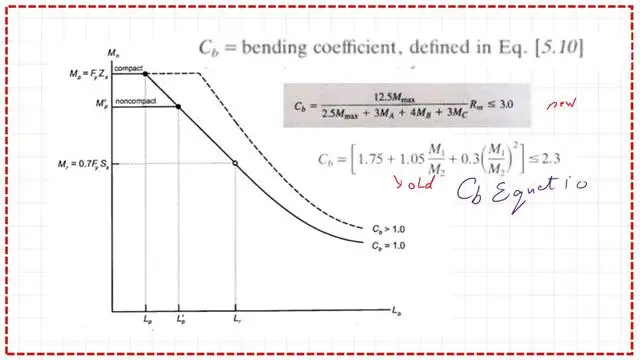
A new factor will be considered: the Cb= bending coefficient, defined in equation 5.10. This factor appears in the three Regions for Lateral-torsional buckling of beams in the equations F2-1, F2-2, and F2-3.
The recent equation for the Cb equals 12.50 *M-max/(2.50 Mmax+3Mb+4Mb+3Mc)*Rm<=3.0.
The factor 12.5 in the numerator equals the sum of 2.50+3+4+3 in the denominator; the item M max is the maximum moment in the beam, divided into three points: A, B, and C.
We will discuss later the Cb with solved examples, while the old equation was Cb=(1.75+1.05*M1/M2+0.30*(M1/M2)^2)<=2.30.
The first part of the curve for Cb=1, but Cb, due to bracing, can be >1. The three Regions for Lateral-torsional buckling for beams can be seen in Mp. The second inclined line joins Mp with Mr = 0.70*Fy*Sx, while when cb > 1.
The horizontal line extends horizontally, and the inclined line will be displaced in case of Cb>1.
How do you evaluate Mn in case of lateral-torsional buckling?
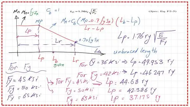
The most essential item for us is determining the relationship between the bracing length and Lp and Lr. How can we estimate Lp and Lr? How do we get the value of Mn in the case of lateral-torsional buckling?
For the case of Cb=1, the horizontal line has a value of Mp, while the inclined line joining two points has a first point of Mp at the unbraced length of Lp and a second point of 0.70*Fy*Sx.
Lp value according to E, Fy, and ry.
There is a relation between Lp and ry, or the radius of gyration in the y direction, and Fy, which is the yield stress of steel based on the designated ASTM.
Mn for any point, if we have a bracing length =Lb between Lp and Lr, can be evaluated as Mn= MP—slope by the difference, then Mn=(Mp—0.70*Fy*Sx) /Lr- Lp all *(Lb -LP)*Cb, Lp value =ry *300/ sqrt FY. The Fy values are listed along with their corresponding Lp values.
The following slide lists the different values of Fy, starting from yield stresses of 36 ksi, 42 ksi, 45 ksi, and 50 ksi and ending with Fy=65 ksi.
For instance, for Fy=36 KSI, Lp=50*ry, where ry is the radius of gyration at the y-axis. For Fy=42 KSI, then Lp=46.247*ry.
For Fy=45 KSI, then Lp=44.68*ry. For Fy=65 KSI, then Lp=37.175*ry.
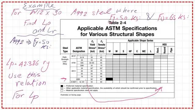
Find Lp for W12x30 A992 steel.
For an A992 steel, the LP value for W12x30 is required. We use Table 2-4 to find the value of Fy for A992 steel. That table indicates that Fy = 50 ksi. The value of lp is equal to 42.386*ry.
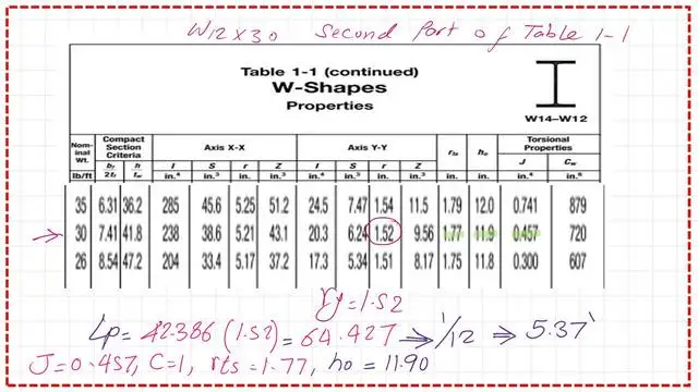
We use Table 1-1, part 2, for W12x30 to find the radius of gyration about the y-axis, which is equal to 1.52 inches. The final value of Lp equals 64.427 inches, which equals 5.37 feet. it is necessary to get the values of rts,c, and h0 for the requirement of Lr.
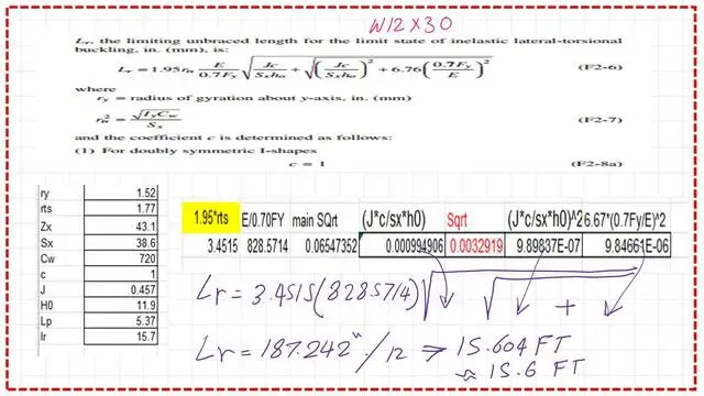
How do we get the Lr value for W12x30?
To find the value of lr, we use a lengthy equation for Lr. Please refer to the next slide for the estimation of Lr. As we can see, lr equals 187.24 inches and can be approximated to 15.60 ft.
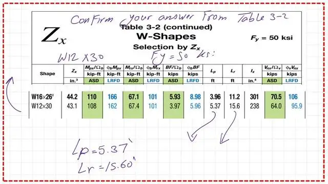
Confirm the value of Lp and Lr from Table 3-2.
We can confirm the values of lp and lr for W12x30 by using Table 3-2 where w sections are sorted by Zx.
The PDF for the data of this post and the previous one can be reviewed or downloaded.
Here is the link to Chapter 8, “Bending Members.” A Beginner’s Guide to the Steel Construction Manual, 14th ed.
Here is the link to Chapter 8, “Bending Members.” A Beginner’s Guide to the Steel Construction Manual, 15th ed.
Here is the link to Chapter 8, “Bending Members.” A Beginner’s Guide to the Steel Construction Manual, 16th ed.
The next post, post 11, is a Solved problem 4-5-How to design a steel beam?