
Last Updated on September 14, 2026 by Maged kamel
Sol
- Solved problem 4- 5: Design a steel Beam (lb less than lp).
- A solved problem 4- 5: Problem statement.
- Design the Beam according to LRFD for Part A.
- Design of the Beam according to ASD for part a.
- Check your understanding by solving the following Quiz.
- Design the Beam according to LRFD for Part B.
- Design of the Beam according to ASD for part b.
- Download the full PDF solution.
Solved problem 4- 5: Design a steel Beam (lb less than lp).
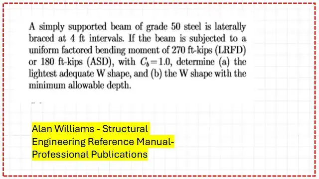
A solved problem 4- 5: Problem statement.
A solved problem 4-5 is quoted from Prof. Williams’ Structural Engineering Reference Manual, 8th edition, based on various given Ultimate /working moments and a given bracing length. As a first requirement, the lightest W section must be determined, and a W shape with minimum allowable depth must be selected as a second option.
Design the Beam according to LRFD for Part A.
Part A includes selecting the lightest adequate W section for design. We must identify which region the section is in based on bracing. This is a design problem for which the distance between bracing for a Beam is Lb < Lp.
For the LRFD design:
1-Estimate the preliminary Zx Value by assuming φbMn = Mult. Since Mn = Zx*Fy, we can find Zx, which will be equal to 72 in^3.
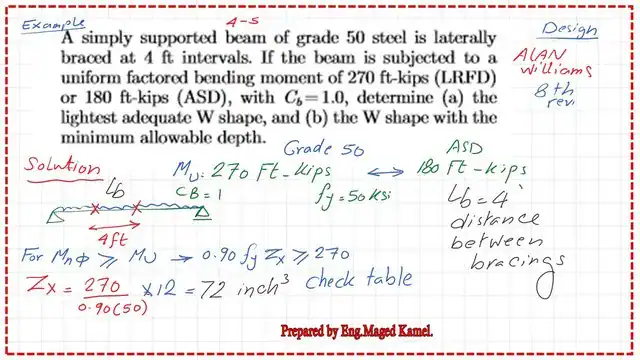
The next slide shows a sketch of how Tables 1-1 and 3-2 can be used to select the required section and find the design strength.
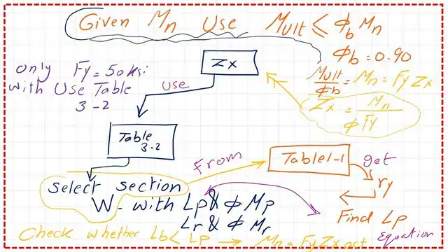
We can get the plastic section modulus Zx = Mult/(φb*Fy). Go to Table 3-2, where sections are sorted by Zx, and select the first bold section with Zx> Zx estimated.
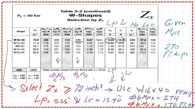
2- From Table 3-2, we get the first bold section, W16x 40, which has Zx = 73.0 in^3> 72.0 in^3 Value required by the preliminary Value for Zx.
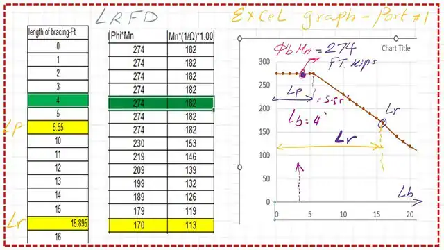
The required bracing length can be obtained from Table 3-2 at the plastic-stage Lp and Lr values. The Lp Value is 5.55 FT, while Lr is 15.90 ft. We used a bracing length of 4 ft, which indicates we are in Zone 1.
The steel section W16x40 has no f symbol, indicating no local buckling.
This is a reminder about the Mn graph, the bracing distance, and the different zones—the Value of Lp according to Fy and the radius of Gyration ry. The x-axis represents the bracing length, and the y-axis represents the Nominal moments.
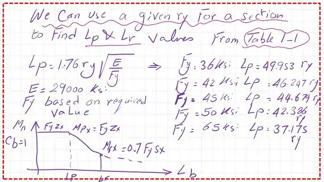
3- From Table 1-1, we can check the Lp Value and find the φb*Mn.
This is part 2 of Table 1-1 for W actions with Fy = 50 ksi. Based on the Beam weight of 40 lb/linear ft, the radius of Gyration is about y =1.57 inches.
The section is compact since the given bracing length Lb is smaller than Lp. The Value of φb*Mn= φb*Zx*Fy is to be divided by 12 to get the Value in ft-kips (LRFD). 4-We get φb*Mn = 274 ft-kips.
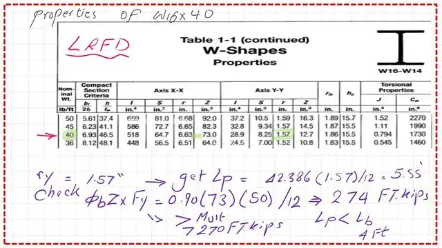
The exact Value of φb*Mn can be obtained from Table 3-2, as seen in the next slide.
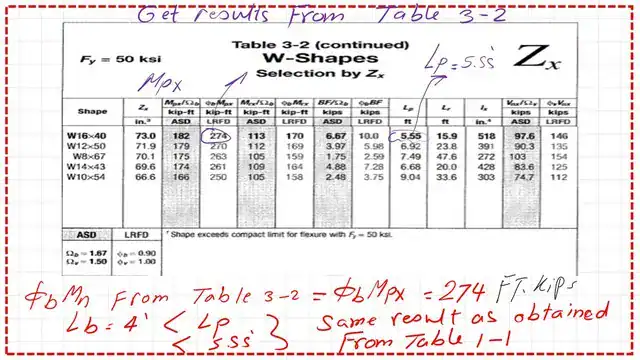
We can see that φb*Mn is bigger than the given ultimate Moment of 270 ft-kips.
Design of the Beam according to ASD for part a.
The ASD calculation is shown in the next slide; here are the following steps to implement:
1-Get a preliminary Zx Value by considering that (1//Ω)*Mn=Mtotal, since Mn=Zx*Fy.
We can get Zx= Mtotal /(1/Ω)*Fy). 2- From Table 3-2, select the lightest W section that gives Zx>Zx preliminary.

The selected W section is W16x40, and its Zx is 73.00 inch3, which is >72.144 inch3, as required.
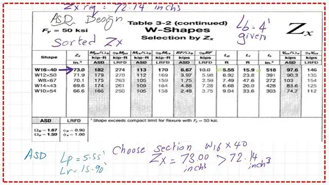
2—From Table 3-2, we get the section W16x 40 with Zx = 73.0 in^3> 72.0 in^3, the preliminary Value for Zx.
The required required bracing length can be obtained from Table 3-2 at the plastic stage,, Lp. Lp can be estimated from the relevant formula Lp = ry* (300/sqrt(Fy)), but we need the ry Value.
3- From Table 1-1, get the Sx Value, ry, for the selected section. Find the Value of lp.
4- Since the given bracing length Lb is smaller than Lp, the section is compact. (1/ Ω)*Mn = (1/ Ω)*Zx*Fy, to be divided by 12 to get the Value in Ft-kips-ASD.
5- Check that the estimate (1/ Ω)*Mn is > the total Moment Mt.
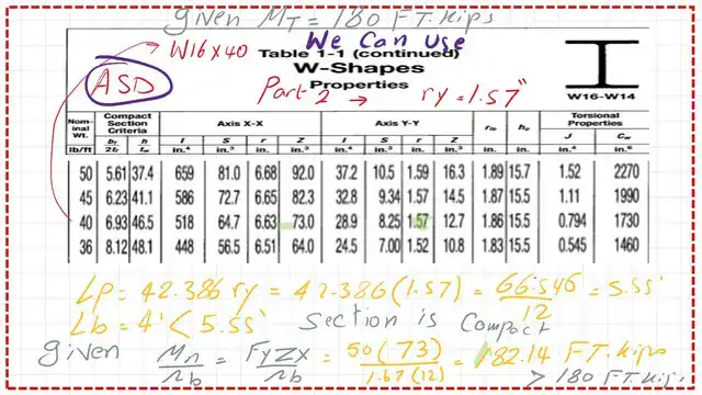
The exact Value (1/ Ω)*Mn can be obtained from Table 3-2, as seen in the next slide.
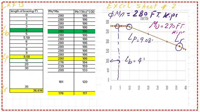
I have added two graphs from an Excel sheet showing the values of φb*Mn and (1/ω)*Mn for a bracing length of 4 feet; the section is W16x40, part a.

Check your understanding by solving the following Quiz.
Two quizzes are available to check your understanding. Please sign in to get verification of your answer via email.
Results
The lp value equals=1.76ry*sqrt(E/Fy). For fy=36 ksi, lp=49.953*ry.since ry=1.57″, lp=49.953*1.57=78.43 inches=6.54 feet.


HD Quiz powered by harmonic design
#1. What is the plastic bracing length lp for W16x40 steel beam of steel grade 36?
The lp value equals=1.76ry*sqrt(E/Fy). For Fy=36 ksi, lp=49.953*ry.since ry=1.57″, lp=49.953*1.57=78.43 inches=6.54 feet.
#2. What is the plastic Moment for W10x60 of grade 36? Select the closest answer from the following choices.
The plastic moment = FyZx = 36*74.60 = 2685.6 inch-kips; dividing by 12, we get 223.8 approximately=224 ft. kips.
Design the Beam according to LRFD for Part B.
Why do we select W10x60?
Part B determines the W-shape with the minimum allowable depth, as per LRFD.
We select it based on the minimum depth. We will select W10x60 since the depth is smaller < depth of W16x40, as shown in the next slide, then check that φb*Mn> Mult.
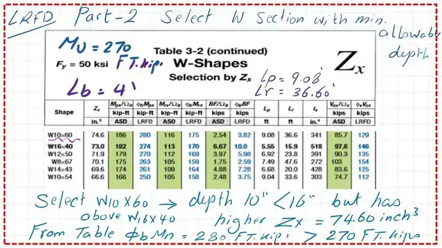
The φb*Mn of the selected section is bigger than 270 ft. kips.
Design of the Beam according to ASD for part b.
This is part b: a W-shape with minimum allowable depth, as per ASD, for the selection based on the minimum depth.
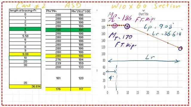
We will select W10x60 since its depth is smaller than that of W16x40, as shown in the next slide, and then check that (1/ω)*Mn > Mt.
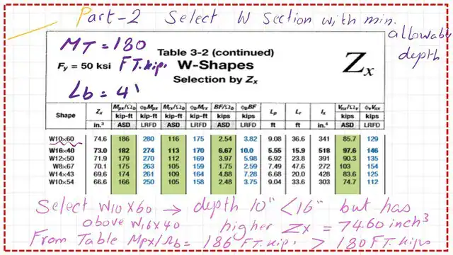
I have added two graphs from an Excel sheet to illustrate the values of φb*Mn and (1/Ω)*Mn for a bracing length of 4 feet; the section used is W10x60 for part b. Thanks a lot.
Download the full PDF solution.
You can review and download the PDF file containing the data for this post by clicking the next button.
This worked solution follows AISC provisions for designing a steel Beam when the unbraced length, lb, is less than the span, lp.
For a valuable external source, please follow this Link: Lateral Torsional Buckling Limit State Beginner’s Guide to the Steel Construction Manual, 16th ed.
Chapter 8 – Bending Members
Review the information on Lpp and Lr for the next post no 12. This post introduces the different terms for Lp and Lr for a steel beam.