
Last Updated on February 23, 2026 by Maged kamel
- Solved problem 12-1-part 2- Find connection nominal load.
Solved problem 12-1-part 2- Find connection nominal load.
The following slide image shows a summary of the content of this post.

We will estimate the nominal shear of fasteners by using Table J3.2.
We can find the bearing Nominal load from Table 7-4, which provides the available bearing strength for the external bolts. There is no provision in Table 7-5 for external bolts of the outer distance of the bolt with the value of le=3″.
Finally, we find out the design strength of the connection after comparing the least load of the different nominal loads for tensile failure, bearing strength, and shear strength.
We continue our discussion of the Solved problem 12-1-part 2 for bearing connections, as quoted from Prof. McCormack’s book.
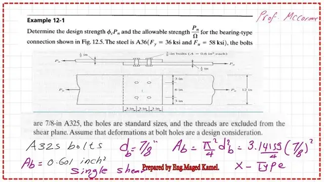
Determine the design strength φ*Pn and the allowable strength Pn/Ω for the bearing-type connection shown in Fig.12-5. The steel is A36, Fy = 36 ksi, and Fu = 58 ksi.
The bolts are 7/8″ in A325, the bolts are standard sizes, and the threads are excluded or X from the shear plane. Assume that deformations at bolt holes are a design consideration.
Solved problem 12-1-part 2. Shear Failure nominal load by Table J3.2.
The next step will be the shear estimation. For shear, we need Table J3.2. For ASTM A325, we have two figures. The first one is for shear, with 54 ksi and 68 kips. Which value should I choose?
The solved problem stated that bolts are excluded, and the thread will not contribute to the shear strength (Fnv = 68 ksi) in estimating shear. The shear calculation checks the number of planes and calculates the area used for shear estimation.
We have two methods. The first method is to use Table 7-1, which provides the available shear strength for bolts.
We have N and X; we check the diameter, and the Table also provides the bolt check diameter area. Each bolt has a 7/8-inch diameter and is an X-type bolt.
We have d=7/8″ for x, and we have S and D, where S is the single shear, and D is the double shear.
To get the shear value for the four bolts, we multiply the Area of each bolt by the Fnv value. The area of one bolt is 0.601 inch2. The shear value for all bolts equals 68*0.601*4=16.472 kips. The Lrfd Φ value =0.75
Φ*Rnv=0.75*163.472=122.60 kips. For the ASD value, we have Ω = 2; the Rnv/Ω = (1/2) * 163.472 = 81.736 kips. Please refer to the next slide image for more details.

A solved problem 12-1-part 2. Shear Failure nominal load by Table 7-1.
We can refer to Table 7-1 for the available shear strength of bolts. Select the column of 7/8″ with the thread condition x as a horizontal line.
The intersected value will be Φ*Rn =30.70 kips for one bolt. For the ASD value, we have (1/Ω)*Rn = 20.40 kips.
How many bolts do we have? We have four bolts, then multiply by 4. For Φ*Rn*n=4*30.70 =122.80 kips.
For the ASD, we have (1/Ω)*Rn*n = 20.40*4 = 81.60 kips. The block shear was not included in the given solved problem 12-1, part 2.

Solved problem 12-1-part 2-Bearing Failure nominal load by Table 7-4.
Table 7-4 provides the available bearing strength at the bolt, based on bolt diameter, bolt type, Fu, and inner spacing. The following slide shows the bearing strength values evaluated in part 1 of the same solved problem.

We have 7/8″ and Fult=58 ksi and a standard hole STD. The spacing between bolts is 3 “.
Move horizontally at a spacing of 3″, intersecting with the vertical line from the nominal diameter of 7/8″ at Φ*rn. We get the value of Φ*rn = 91.40 kips/inch of plate thickness. Since the plate thickness is 1/2″. Then multiply by (1/2).
We get the design value ASD value of rn from the same Table when selecting Move horizontally at the spacing of 3″, which intersects with the vertical line from the nominal diameter of 7/8″ at (1/Ω) *rn.
We get the value (1/Ω) * rn = 60.90 kips/inch of plate thickness. Since the plate thickness is 1/2″, then multiply by (1/2). For a single bolt, but/inch of plate thickness, our plate thickness is 1/2″.

LRFD value for bearing.
From Table 7-4, we have Φ*rn=91.4 kips/inch, then multiply by 1/2″, the final Φ*Rn=45.70 kips for one bolt.
ASD value for bearing.
For the (1/Ω)*rn=60.90 kips/inch, then multiply by 1/2″, the final (1/Ω)*Rn=30.45 kips for one bolt. The calculations are very close to those done previously using equations.

Solved problem 12-1-part 2—the final summary for the nominal load.
We compile all the estimated values into a Table, which is presented below.
This is the summary for yielding for LRFD Φ*Rn=194.40 kips, for fracture Φ*Rn=261 kips. In the case of shear, Φ*Rn=122.60 kips. You can double-check the values by dividing the LRFD by 1.5 to get the corresponding ASD values. Ω =1.50. What are the lowest values? The lowest value is 122.60 kips from LRFD shear.

The final value of Φ*Rn = 122.55 kips, and the values for the ASD design nominal loads are added for each limit state. The final ASD value selected is 81.74 kips.

Thank you very much, and I look forward to seeing you in the next post.
The PDF for this post can be viewed or downloaded from the following link.
This link is for the previous post, which solved problem 12-1 for bearing connections.
This is a link to a Solved problem 5-part 1 for design shear strength for bolts.
This is a very useful source for the design of various Steel elements, A Beginner’s Guide to the Steel Construction Manual, 15th ed, Chapter 4 – Bolted Connections.
This is a very useful source for the design of various Steel elements, A Beginner’s Guide to the Steel Construction Manual, 16th ed, Chapter 4 – Bolted Connections.