
Last Updated on February 23, 2026 by Maged kamel
Solved problem 12-1 for bearing connections.
The following slide image shows a summary of the content of This post.

The following slide image shows a review of the different modes of failure for bearing connection Quoted from The Applied Strength of Materials Book By Robert Mott, chapter 13.

A Solved problem for bearing connection 12-1-Part 1.
Our new topic will be the discussion of problem 12-1 from Prof. McCormack’s book, which has been solved.
Determine the design strength φ*Pn and the allowable strength Pn/Ω for the bearing type connection shown in Fig.12-5. The steel is A36 where (Fy=36 KSi) and Fu=58 ksi, the bolts are 7/8″ in A325, the bolts are standard sizes, and the threads are excluded or X from the shear plane. Assume that deformations at bolt holes are a design consideration.
The overlap distance is length =9″, where the CL distance=3″ between bolts. The length is in the direction of the load, while the transverse cL distance =6″. The edge distance is 3″ and 3″ from each side.

Tensile Failure nominal load by Yielding for solved problem 12-1.
For this connection, we have two modes of failure. The first mode of failure is due to yielding as shown in sec 1-1, and the mode of failure is to rupture as shown in sec II-II. Please refer to the next image for section 1-1.

We have a single-shear plane. Two plates are placed on top of each other and connected by 4 bolts. The bolts are 7/8″, where the area for each bolt=0.60 inch2 as given.
The upper plate is 1/2″, the lower plate thickness is 1/2″, and the plate width is given as 12″.
For the tensile yielding Fy to be multiplied by Ag, or the gross area. In the second case, by tensile rupture, the area net is to be multiplied by Fult.
We are aware that, due to placing bolts during installation, we add 1/16″+1/16″ to the diameter of one bolt, which is 7/8″, then the final value considered for diameter=7/8+2*(1/16)=1″.
For the first case, the area gross = 12 × 1/2 = 6 in².

Then, the tensile yielding = Ag* Fy; we have Fy = 36 ksi and Fult = 58 ksi, Ag = 6 in^2, then Rn = Ag*Fy = 36*6 = 216 kips. For the LRFD, φ=0.90, φ*Rn=0.90*216=194.4 kips.
While for allowable design (1/Ω)*Rn, where Ω=1.67.
Tensile Failure nominal load by rupture for solved problem 12-1.
For case b) where Area gross- 2*diameter*thickness of the plate. Anet =12*1/2- 2*(1))*1/2.
The net area, Anet, is 5 inches². Since we are dealing with the net area, we use Fult of 58 ksi.Rn=5*58=290 kips.
Remember from the tension area lecture that Aeff = U*Anet; U = 1 for plates, so Aeff = 1*5 = 5 in^2. But now φ=0.75, and Ω=2 .φ*Rn=0.75*290=217.50 kips. While Rn/Ω=290/2=145 kips.

The calculation of bearing for the solved problem 12-1.
Before checking the bearing capacity of the bolts, we need to review the list of tables required for our estimation.
The diameter of bolts=7/8″, the hole diameter is the bolt diameter plus 1/16″, and the diameter hole equals 15/16″—the inner spacing is 2 2/3 db.
To check the requirement of the edge distance, there is Table J3.4 for a 7/8″ bolt; the required edge distance is 1/18″

To check the requirement of the edge distance, refer to Table J3.4 for a 7/8″ bolt, where the required edge distance is 1/18″. The minimum spacing between bolts is 2.32 inches for db = 7/8 inches.

We have a distance from cl to the outer edge of 3″, which satisfies the case since this distance is greater than 1 1/8″, as given in the table.
For the spacing requirements for inner bolts, the spacing value is 3 inches, which is bigger than 2.33 inches, which is the minimum requirement.


Nominal bearing value for the external bolts.
The next step is to estimate the nominal bearing value for the external bolts. We estimate the clear distance to be 2.531 inches.

We compare this value with the value of (2db). We find that the outer clear distance for the exterior bolt is bigger than 2db, which indicates that the nominal value is governed by the upper limit equation, which is(2.4*d*t*Fu). The details of the estimation can be found on the next slide.

Nominal bearing value for the inner bolts.
We will estimate the nominal bearing value for the inner bolts. We estimate the clear distance to be 2.06 inches.
We compare this value with the value of (2db). We find that the outer clear distance for the exterior bolt exceeds 2db, indicating that the nominal value is governed by the upper limit equation (2.4*d*t*fu). The details of the estimation can be found on the next slide.
The upper limit is 2.4d*b*t*Fult, db=7/8″ *t=1/2 for a plate, which is common between the left and right sides of the equation.
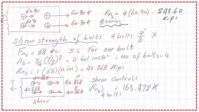
The upper limit value will be equal to 2.4*7/8*1/2*58=60.90 kips. The nominal load based on equation (1.2*lci*t*fu) is shown, and as we can see, it is higher than the upper limit and is not considered in the design.

Nominal strength value for bolts.
The next step is to estimate the shear strength of the bolts. There are two ways to estimate. The first way is to use Table J3.2 to obtain the Fnv based on the bolt type. In our problem, the bolt is 7/8-inch X type A. Fnv value is 68 ksi, a single-shear value for one bolt.

I have included two sketches for comparison between the bolt’s nominal loads in bearing and the corresponding bolts, but with the shear strength. It can be seen that the shear strength of the bolts is less than the nominal load, as bearing and shear strength control the design.
We will continue in the next post to finalize the calculations for the given connection. Thank you.
The PDF for this post can be viewed or downloaded from the following link.
The next post will be A solved problem 12-1-part 2-connection nominal load.
This is a very useful source for the design of various Steel elements, A Beginner’s Guide to the Steel Construction Manual, 15th ed, Chapter 4 – Bolted Connections.
This is a very useful source for the design of various Steel elements, A Beginner’s Guide to the Steel Construction Manual, 16th ed, Chapter 4 – Bolted Connections.