
The introduction to lower bound and uniqueness theorem.
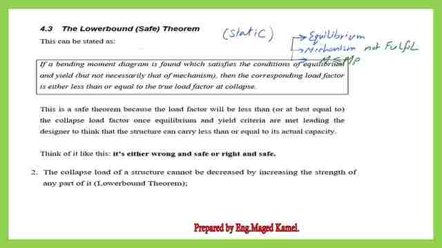
This is the definition of the lower bound (safe theorem), if the bending is found to satisfy the conditions of equilibrium and yield (but not necessarily that of mechanism), then the corresponding load factor is either less than or equal to the true load factor at collapse.
What is the Uniqueness theorem?
The third theory is the Uniqueness theorem. The solution is unique. If we work with the upper bound for several points and obtain the value, the lowest value of Mp, then the solution is the true value.
Here is a sketch, there are three important factors, the first point is the equilibrium for which we get the same value of Mp at the same point from the left side or to the right side. The second point is the mechanism in which we convert the system unstable by adding 1 to the number of indeterminacy.
The yield is bending moment must be for Mp is the biggest value in the diagram.
In the Upperbound the λ>=λc, where λc is the exact ratio at collapse= collapse load/working load. While in the lower bound λ<=λc, where λc is the exact ratio at collapse= collapse load/working load. for the last theorem, it gives λ=λc.

Different selections for locations of the plastic hinges.
The plastic hinges between joints A &C.
We are going to check an example, to examine a different selection of locations for a plastic hinge using the lower bound and upper bound side by side.
In our previous example, our selected plastic hinge was at point c where the load acts, if somebody else selects another point, say point d between points A and C.
The distance d is at 0.20 m distance from joint A, let us check the mechanism due to that selection.
The number of inderteminancy=3+1-3=1, we need two joints to create a mechanism. We have two hinges one at A and the second one at d.
We will use the kinematic or virtual work, we have a negative Mp at joint A and a positive Mp at joint d The deflection at point d is Δ.
For the angle α at joint A, the slope tan α= α=Δ/0.20. Let the slope at the joint b is, the distance d- b is=1-02.0=0.80 m. Angle β=tan β=Δ/0.80, we have Mp acting at d with an angle = α+ β.
The external work at C= the internal work, note that 32*λ*(deflection underneath the load).=32*λ*(0.50/0.80)* Δ =32*λ*(5/8)* Δ = the internal work= Mp*α+Mp*(α+ β )=Mp*(Δ/0.20)+Mp*((Δ/0.20)+(Δ/0.80)).
32*λ*5/8*Δ=20*λ*Δ=Mp*( 0.20)+Mp*(5*Δ/0.80)=Mp*(4Δ+5Δ)/0.80)=9*Mp*Δ/0.80.20*λ=9*Mp/0.80, Mp is given as 9.0 KN.m 20*λ=81/0.80=101.26, λ=5.0625.
Let us check that the Mp value at the right and the left side have the same value and the same λ is unique, the reaction = 16*λ+9/1, the moment at the left of d=(16*λ+9/1)*0.20+Mp=Mp.(16*λ+9/1)*0.20+(-9)=9, 3.2*λ-9+1.80=9, 3.2*λ=16.20, λ=16.20/3.20=5.0625, which is the same value.
The load (32*λ)=32*5.0625=162.0KN, Ra=90 Kn, Rb=72 KN. We will draw the Bending diagram and check is it safe or not? The moment at point d =9.0 KN.M, but if we estimate the moment at C. Mc=72*0.50=36.0 KN.M is drawn in the small sketch.
The estimated Mp is at d=9.0 KN.M, but this assumption will lead to the moment at C=36.0 KN.M, but the Mp which is 9.0 KN.M is considered to be the maximum value that the section can carry.
It is not permitted to have a higher value at C =36.0 KN.M, so while performing the assumption of the point. we have to be sure that no value for the moment is higher than Mp, that is why it is an upper-bound theorem. A thorough check is to be conducted for several points.

The plastic hinges between joints C &B.
Another selection for a plastic hinge, If somebody selects the plastic hinge location at d between C and B at a distance of 0.20 m from Joint B. Again the angle at Joint A is α, and the angle at Joint B is β, the deflection at point d is Δ.
The deflection value under the load will be a fraction of Δ, the distance A-C=0.50m, but tan α=α=Δ/0.70, the deflection at C=(0.50/0.80)*Δ=(5/8)*Δ, tan β =Δ/0.20.
The external work at d= internal work, then 32*λ*(deflection underneath the load)=32*λ*((5/8)*Δ)=Mp*α+Mp*(α+β), consider α=Δ/0.80. while β=Δ/0.20, 20*λ*Δ=Mp*(Δ/0.80+(Δ/0.80)+(Δ/0.20)=Mp*Δ*(6/0.80), Mp=9.0 KN.M.
λ=3.375, we will check from the RHS and let Mp=9.0 KN.M.
Then Rb=(16*λ-9), the Md=16*λ-9)*0.20=9.00, we will have the same value of λ=3.375, we will draw the bending moment diagram after substituting the value of λ=3.375 to get Ra=16*3.375+9=63 KN and Rb=16*3.375-9=45 KN. The bending moment is drawn. The load at C=32λ=323.375 =108 KN, the moment at c=63*0.50-9=23.50 KN.M. While the Mp, which is the maximum value=9.0 KN.M

The selection of the hinge at the right of point C is a wrong choice because it leads to a higher moment >Mp at point C.
The Graph for the value of Mp is based on the locations of the plastic hinges.
The next page shows a graph where the horizontal axis is the distance in m from support A as (1-a), while the y-axis represents the value of λ, the first choice where the hinge is at the left side where 1-a=0.20 m,a=0.80 m, the distance from the right support at B.
For a plastic hinge at the left of point c, λ=(9/16) *(a+1)/(1-a), this relation gives a curved shape, for every change of the value of a, there is a corresponding λ value. for 1-a=0.20 m, a=0.80 m.
While the plastic hinge location was chosen to be between C and B. Another curve is given, a is also estimated as the distance from the right support B a distance=0.20m. The distance a is also estimated as the distance from the right support B, a distance=0.20m , λ= (9/16)*(1+a)/a=(9/16)*(1.0+0.20)/0.20)=(9/16)*(1.0+0.20)/0.20)=54/16 =3.375, which is represented by this point on the graph.
What is the correct selection?
It is the minimum λ or the minimum value of P collapse λ=1.6875. There is another way that we can get the value of Mp as a function of x, where x is the distance from the left support.
While the remaining distance will be L-x where l is the span distance, then we can see that in analyzing the proposed collapse we either correct, λc=1.6875 or we are unsafe λ>λc, this is why plastic analysis is an upper bound method.

This is the pdf file used in the illustration of this post and the previous post.
For useful information about the structural analysis -III.
For the next post, a plastic moment for continuous beams.