Last Updated on November 24, 2025 by Maged kamel
Stiffness reduction factor for inelastic columns.
Introduction to the Tangent modulus of elasticity.
This is a new subject, for which we will talk about the difference between the modulus of elasticity E and the other modulus of elasticity Et, which is the tangent modulus of elasticity, and under what conditions do we use the Et?

The second point, after God’s well, τb, or the stress reduction factor, is for the case of short or medium columns.
In front of you is the slide, quoted from Prof. Segui’s book, page no.114, in brief. The long columns, the compression stress for these columns, just only reaches the Proportional limit stress, which is a portion of Fy.
He pointed out in the solved example 4-1, that the stress at buckling is Pcr/A, Pcr is the critical load and A is the area.
The value is =19.10 ksi, which is well below the proportion limit for any grade of structural steel. Thus, for long columns, the stress on that column will be nearly equal to the stress at the proportional limit or smaller.
For inelastic columns, such as short or intermediate columns, residual stress is created due to the change in temperature during the fabrication process, resulting in variations in stresses within the structural steel column.
Accordingly, there is a change in the relation to the graph between stress and strain, for a column, which can be represented by an inclined line, up to the proportional limit stress, followed by a curved graph till failure occurs.
Introduction to a new value of E, which is Et.
Then, the question will be how to estimate the modulus of elasticity for the short or Intermediate column. Prof. Fredric Engesser has proposed several trials, using the slope values between the proportional limit point and the failure point. He has proposed a new tangent modulus of elasticity for Short and Intermediate columns.
The Euler equation Pcr=π^2EI/L^2, for the elastic failure, the expression can be modified to become, after replacing the E expression since by Et, Pcr=π^2Et*I/L^2, since the slope, Et is smaller than E slope at the Euler equation, or the initial modulus of elasticity.

For any material, the critical buckling stress can be plotted as a function of slenderness as shown in Figure 4.6. Later, the new studies proved that we can use his method as follows, for the first part of the graph between L/r and Fcr.
If we extend the slope of the Fcr=π^2*E/(l/r)^2 at the point at which Fcr=Fy/2.25, it represents the point at which we differentiate between long and short columns.
As we remember that at the point of Kl/r, or le/r=4.71*sqrt(E/fy), then there will be another curve, for which we estimate the proposed critical stress by the AISC equation.
Suppose we fit the two curves, one for elastic buckling and the other for inelastic buckling, so that they become tangent to each other. When curves are tangents, then the left side curve represents the inelastic columns, and we can write the expression for Fcr π^2* Et/(l/r)^2.
Now, for the inelastic buckling zone for any value of Kl/r, compare the values estimated by the Fcr estimated by the Euler equation, and the value calculated by using the Engesser equation.

We will find that Fcr inelastic is< Fcr from Euler’s equation, then Fcr inelastic/ Fcr elastic is called τ and is <1.
The modified value of the stiffness ratio at a joint in terms of E and the stiffness reduction factor.
How to use this information for the alignment chart for columns?
For instance, if we have a column line A’AB, column AB is elastic, while the intersection beams are elastic. The column intersects with two beams, EB and BF. The G value at joint b is represented as Gb=∑EI/L column/=∑EI/L beam. The E will be eliminated.

Let Et/E=τb, which is the stiffness reduction factor. The column behaves inelastically, as indicated by the yellow part of the graph, with E = Et, and the G value will be modified to Be G inelastic.

Consider the case of elastic columns and elastic beams, E will cancel each other, then G elastic=(Ic/Ib)*(Lb/Lc), while G inelastic= τb*(Ic/Ib)*(Lb/Lc) = G elastic*τb, τb=Et/E <1.
At P-117, we quote that the column buckling problem can also be formulated in terms of fourth-order differential equations. This proves convenient when dealing with boundary conditions other than pinned ends. Hence, the k value can be included in the equation.
Pcr at elastic failure=Pcr=π^2E*A/(k*L)^2, or for inelastic columns, Pcr=π^2Et*A/(k*L)^2. Columns given by 4.6b, when divided by the cross-sectional area, provide the buckling stress.

The Fcr value is obtained by dividing Pcr by the area. Fcr inelastic =π^2Et*/(k*L)^2, and G- inelastic=G-elastic*Et/E which is τb.
The next slide shows the Johnson graph for which Fcr=Fy-Fy^2*(Kl/r)^2*(1/4*pi^2*E).
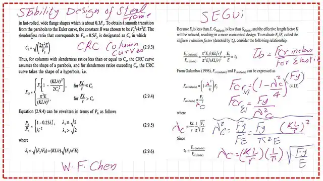
The term (λ^2) is introduced as equal to Fy/Fe, which will modify the Johnson equation to Fcr in=Fy(1-λ^2/4), for the tau value at the point where λ^2=2.0, Fe=Fcr inelastic, and the tau value τb=1.00, which is applied for the LRFD design.

From Galamblos’ two expressions, Fcr inelastic (1-λc^2/4)*Fy, and the second expression is Fcr in=Fy/λc^2, where λc^2 =Fy/FE, where FE is the Euler stress according to the elastic curve. The value of λc is shown in the next slide.

In the next slide, we see the different methods used to develop expressions for column design equations. We will be concerned with the first two equations based on CRc curves, where λc^2 = 2.00.

We will continue discussing the inelastic columns equations in the next post.
A handy external link is Chapter 7 – Concentrically Loaded Compression Members.
The following post will be a Stiffness reduction factor for inelastic columns-part 2.