Last Updated on February 23, 2026 by Maged kamel
Bearing Type connections-part-1.
Detailed content
In this post, Bearing Type connections-part-1, a picture shows a steelworker using a spanner to check that all bolts are snugly tight. This type, for which the wrench is used, is called the bearing type.
In the bearing type, the load is transferred between members by bearing on the bolts, using a wrench.
The second type is the slip critical; for example, if a tire needs to be replaced, a tire fixer will repair the car tire and then use a gun with a compressor, called an impact wrench or a Torque Wrench. In the next image on the right, a worker is fixing bolts with a calibrated wrench.

Types of bearing bolts.
In the bearing type connections-part-1.We proceed to the next slide, and the bearing type is classified into two parts.
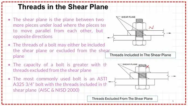
Type N is the type for which the threads are included; as in the previous post, we have included the different parts of the bolts; as shown in the picture on the left, a shear force is developed at the contact plane if the threaded part is included in the shear plane. Then it is called a type N bolt.
N-Included threaded. The connection is a bearing-type connection, and the bolts are installed so that the threads are included in the shear plane(s), either a single plane for single shear or several planes for double shear. Their definitions for these terms are found in the following sections.
X Excluded threaded; the thread, if we refer to the image at the right, is not passing by the shear plane and is excluded using the symbol X or writing ASTM A 325-X. Group A As a summary, then group A -N is a bolt made from ASTM A-325, and the threaded is included, while group A means the bolt is made from ASTM-325 and the threaded is excluded.
While the symbol SC indicates that the connection is slip-critical or pre-tensioned. Due to the bolt’s pre-tension, either friction or slip will occur, resulting in movement.
I quote, for example, that an ASTM-X bolt would be a bolt made from ASTM A325 steel and would be installed such that the threads are excluded from any shear plane(s).
While the A490-SC bolt is made from A490 steel and is installed in a slip-critical connection where the faying surfaces must meet special requirements, let’s examine a bearing connection.

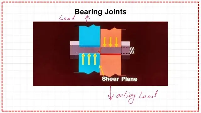
In the next slide, the loads are carried by bearing. The loads attempt to shear the bolt or, under the pressure exerted on it, cause stress in the connection material, which may lead to tearing, as we will see later. The bolt is referred to as a Type N bolt.
The following slide includes the previous information on the threads in the shear plane, including N or X type.
Single shear connection.
I quote from the initial discussion that the reader is referred to part(a) of Figure 12.1. It is assumed that the plates shown are connected with a group of snug, tight bolts.
In other words, the bolts are not tightened sufficiently to squeeze the plates together significantly. If there is assumed to be little friction between the plates, they will slip slightly under applied loads. The loads will tend to shear the connection between the plates or bear against the sides of the bolts.
In a connection, the load P acts to the left, pressing the bolt to the left and causing bearing on the bolt by the value of the load P.
The following slide includes the previous information for the threads in the shear plane, categorized as N or X types.

The Following slide image shows how bearing connections transfer shear from one plate to another.

Types of failure for the bolted joint.
For the next slide, Bearing Type connections-part-1. Failure can occur in the connector or the Connected parts; there are six types of failures for both Types.

The author discusses the types of failures. One type of failure is by rupture that occurs across the line of bolts, perpendicular to the load direction; Anet*U*Fult is the capacity of the section.
Failure may also occur due to bolt shear from two equal and opposite forces acting on the joint, which causes failure when the load exceeds the shear resistance of the single bolt.
The potential failure is plate shearing; please refer to the next slide for more details.

Failure may be due to plate tension failure. A detailed illustration of these types for the bearing type connections-part-1 is included in the next slide image.

The Following slide image shows the Bearing failure of bolts and Plates as case Number 3.

The failure of shearing out of plate-Tear out case 4- and shear failure of the bolts as case 5 are shown in the following slide.

Tension failure of the bolt is another failure mode that can occur.

Double shear connection.
In the next slide, the butt joint or the (double shear) is introduced. In this situation, we have two outer plates and a middle one. A shear may occur in the bolt due to double shear.
The load P, which acts to the right, is transferred to the two plates by a value of P/2 for each plate through the bolt. Referring to picture c), the bearing on the bolt is due to P/2 acting to the left, as shown by the upper left plate.
Balanced by P/2 at the section of the bolt, which again is transferred to load P/2 acts to the right.
Again, there is P/2 from the lower portion. The total load =P, causing bearing on the bolt in the middle section by a value of P to satisfy the equilibrium at the middle portion. For the lower portion, the bearing is P/2.
I quote, ‘The members are arranged so that the total shearing forces are split into two parts, causing the force in the two planes to be only one-half of what it would be on a single plane.’ Therefore, the carrying capacity is theoretically twice as great as the same number of bolts in a single shear.

The bearing on the material around the bolt for the bearing-type connections will be viewed.
We talk about tearing; we have two plates above each other; please refer to Fig.5.4 at the right, as previously discussed, having two plates with force acting to the left, at the part of the bolt p acting to the left is acting against the plane with width d and the section with height =t, the failure will occur if the shear stress is exceeded.
If we have two plates with two different thicknesses, t1 and t2, then select the thinner of the two, t1 or t2.

This is the pdf file for the content of this post.
he next post is Bearing Type connections 2-2.
This is a very useful source for the design of various Steel elements, A Beginner’s Guide to the Steel Construction Manual, 15th ed, Chapter 4 – Bolted Connections.
This is a very useful source for the design of various Steel elements, A Beginner’s Guide to the Steel Construction Manual, 16th ed, Chapter 4 – Bolted Connections.