Last Updated on August 14, 2024 by Maged kamel
- List of Steel Beam Posts-part-3b.
- Deflection of steel beams.
- A solved problem 5.1 from Prof. Fredrick Roland's book- part 2.
- Part 1/4 Solved problem 9-9-6: how to find LL?
- Part 2/4 for the Solved problem 9-9-6, how to find LL?
- Part 3/4 for the Solved problem 9-9-6, how to find LL?
- Part 4/4 for the Solved problem 9-9-6, how do we find LL?
List of Steel Beam Posts-part-3b.
Deflection of steel beams.
The post is part of a list of steel Beam posts-part-3b, including deflection disadvantages.
2-The permitted limits of deflection.
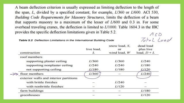
3- What are the Deflection limitations in the unified building code?
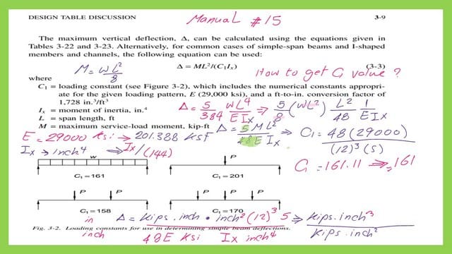
4- What is the C1 coefficient as a deflection parameter by the AISC?
Here is the link for post 24: Deflection of steel beams.
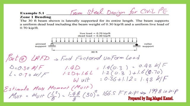
A solved problem 5.1 from Prof. Fredrick Roland’s book. Example 5.1-part 1.
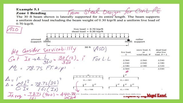
The 30-foot beam is laterally supported for its entire length. It supports a uniform dead load, including a beam weight of 0.30 kip/ft and a uniform live load of 0.70 kip/ft. In the first part, we will find the required moment of inertia value Ix based on the Total load and Ix based on the LL.
Here is a link to post 24a– Easy approach to the solved problem-5-1-part 1-2.
A solved problem 5.1 from Prof. Fredrick Roland’s book- part 2.
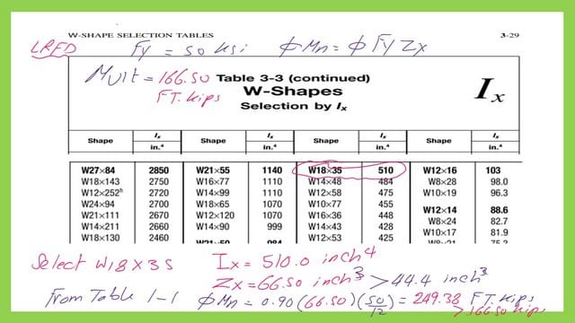
In part 2, we will estimate the ultimate moment in the LRFD design. We will use Table 3-2 to select a W section and check the Ix for the chosen section against Ix values based on deflection. We will use Table 3-3 to select the proper section based on Ix. Check the section chosen for The ASD design.
Here is a link to post 24b– Easy approach to solved problem-5-1-part 2-2.
Part 1/4 Solved problem 9-9-6: how to find LL?
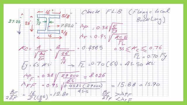
Part 1 includes a solved problem,9-9-6, from Prof. Charles G Salmon’s book. Determine the service live load the beam may carry if the Dead load is 0.15 kip/ft, including the beam weight. Use load and factor design. The steel has Fy=65ksi. The given beam is a built-up beam. We will use Table b4.1B to determine the limiting value for flange and web parameters for local buckling.
The first part of the solution includes determining the lambda coefficients λp-F λr-F, λp-w λr-w for Local buckling for the Flange and the web of the Built-up section.
Both the flange and web sections are Non-Compact sections since the limiting parameters are less than those of lambda Plastic.
Here is the link to post 25 –How to find LL- Part 1/4?
Part 2/4 for the Solved problem 9-9-6, how to find LL?
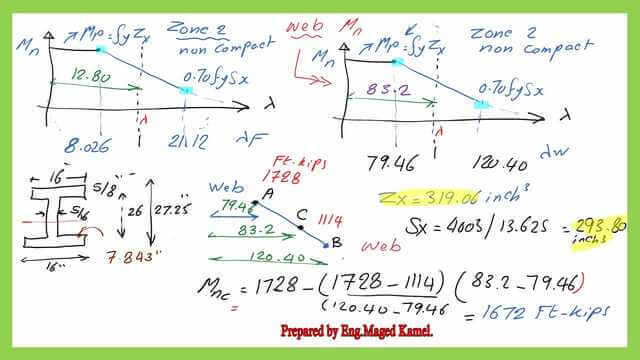
The second part of the solution includes determining the section modulus of elasticity for the Built-up section. Two nominal moments: one is based on the limit state of local buckling for Flange, and the other is based on the local buckling of the web section. After checking the lateral torsional buckling, the final decision on the final value of the nominal moment will be made, which will be included in the next two parts.
Here is the link to post 26- Part-2-4 of the Solved problem 9-9-6, How To Find LL?
Part 3/4 for the Solved problem 9-9-6, how to find LL?
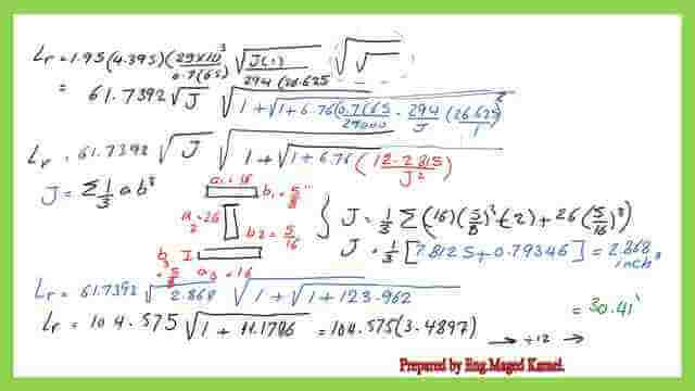
The third part of the solution includes the lateral-torsional buckling parameters Lp and Lr for the built-up section, estimating the value of limiting length lr.
Here is the kink to post 27: Part 3/4 of the Solved problem 9-9-6: How do I find LL?
Part 4/4 for the Solved problem 9-9-6, how do we find LL?
The fourth part of the solution includes evaluating the nominal moment for the section based on the Lateral torsional buckling and then finalizing the LRFD value of the Final nominal moment to estimate the permitted Live load value.
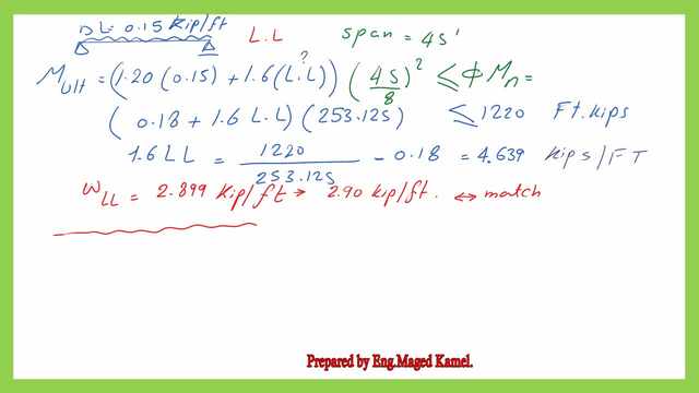
Here is the link to post 28: Part 4/4 Solved problem 9-9-6. How do you find LL?
The next post will be the list of steel beam posts, part 4.
A very useful external resource, A Beginner’s Guide to Structural Engineering