Part 4/4 of the Solved Problem 9-9-6, How To Find LL?
How to estimate the Cb for the beam-Part 4/4 of the Solved Problem 9-9-6.
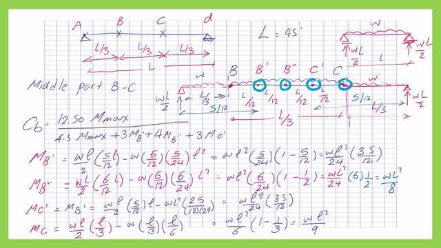
Cb for a simply supported beam under uniformly distributed, this is included in part 4/4 of the Solved Problem 9-9-6. This is a reminder of the Cb value for parts AB and CD.
We have one roller support at one end and a hinged support at the other end.
The bracings spacing is every L/3 distance where L is the span length. We will take the first part of L/3 and magnify it. This is part BC.
The reaction for the beam at the left hinge=W*L/2=Reaction at the right support. We need to estimate the moment values at B’, B”, C’, and C.
The L/3 length is to be divided into four sections. So we have L/12 intervals between these points. Then we can estimate the CB equation. CB=(12.50*M-max)/(2.50 M-max+3*Mb’+4*MB”+3*Mc’)
The next slide image shows the different values for the moment at the four points.


From the next slide. Use the equation of CB=(12.50*M-max)/(2.50 M-max+3*Ma+4*Mb+3*Mc).
The value of Cb=12.50/8*(234+210)/288=1.01, the beam has three values of Cb as (1.46,1.01,1.46), the CB can be used to increase the Mn
How to estimate the Mn for the beam?
The next step is to estimate the Mn value based on the limit state of the lateral-torsional buckling.
We have Lp =12.10′ while Lr = 30.41′, actual bracing length = 15′ as given in the solved problem. We have Mp=1728 at Lb=12.10 and Mr=0.70*Fy*Sx=1114 at Lb=Lr.
At the 15′ distance Mn=Cb* (1728-1728* (1728-1114)/(30.41-12.10)*(15-12.10), if we so we can use cb as=1.01, taken as =1.0 by prof. Salmon.
In the next slide, there is a graph between Lb and Mn values. At Lp=12′ we have Mn=1728 ft, while for Lr=30.41′, Mn=1114 ft. kips.
The Mn value for cb=1.00 will be equal to 1630 ft. kips for the case of lateral torsional buckling. The three values are shown in the slide. This is a reminder of the Mn in the case of flange local buckling.
This is a reminder of the Mn from the case of both the flange and web local buckling.
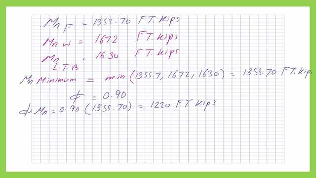
We have three Mn values, one from the local buckling of the flange which is equal to 1355.7 ft-kips. The second value for the Mn, from the local buckling of the web=1672 Ft-kips. The third value for Mn is 1630 ft.kips.
The minimum selected value of Mn is 1355.70 ft-kips.
The LRFD value multiplied by φb will be φb*Mn=0.90*1355.70=1220 ft-kips.


How to estimate the LL for the beam- part 4/4 of the Solved problem 9-9-6?
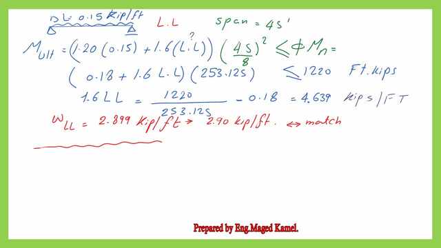
The ultimate load for the simple beam Mult must be =< 1220 ft.kips.
From the next slide, the Dead load included the own weight=(0.15*1.2+1.60*LL)*(45^2)/8<=1220 ft-kips. Then (0.18+1.60*LL)*253.125<=1220. 1.60*LL=(1220/253.125)-0.18=4.639. LL=4.639/1.60=2.899 Kips/ft. Taken as LL=2.90 kip/ft, which matches the final solution by Prof. Salmon. Thanks a lot.


This is the pdf file used in the illustration of this post.
This is the next post, Moment Redistribution For Continuous Steel Beams. The post is an introduction to the method for moment redistribution set the AISc code for the reduction of the negative moments and add 0.10 to the average value between supports to the positive moment.
For useful external resources for steel beams. Chapter 8 – Bending Members

