
Last Updated on September 17, 2026 by Maged kamel
- Solved Problem 10-1, bearing Value-LRFD, part 2 of 3.
- Solved Problem 1: How to calculate bearing and tear-out values for a bearing connection?
- Review the necessary tables for estimating nominal bearing strength.
- The nominal bolt-hole dimension.
- Solved Problem 10-1: How to get the bearing Value (LRFD) for a connection?
- Using Table 7-4 for the nominal bearing Value (LRFD) for inner bolts.
- Use Table 7-5 for the nominal bearing Value (LRFD) for external bolts.
Solved Problem 10-1, bearing Value-LRFD, part 2 of 3.
Solved Problem 1: How to calculate bearing and tear-out values for a bearing connection?
I added a summary of the Post’s content and the requirements for solving Problem 10-1 to the following two slides.
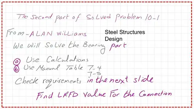
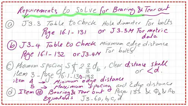
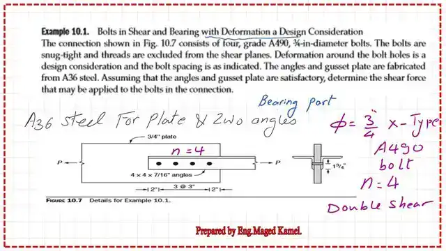
We will review Problem 10-1, specifically the bearing and tear-out part, from Prof. Alan Williams’s book. The second part will estimate the Shear force applied to a connection based on Bolt bearing and tear-out.
Review the necessary tables for estimating nominal bearing strength.
The bearing and Tear-out coefficients for LRFD and ASD are φ = 0.75 and Ω = 2.0. These coefficients are the same as those used to estimate Shear from bolts.
The AISC code specifies bearing and tear-out if deformation is the design criterion.
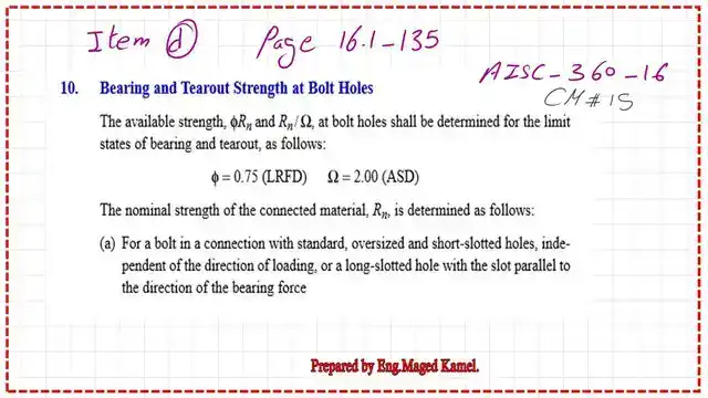
If the deformation = 0.25″, then the upper limit for bearing =2.4*d*t*Fu, where d is the diameter of the Bolt, t is the thickness of the plate, and Fu is the ultimate strength. But if deformation is not a design criterion, then a higher Value is given for Rn = 3.0 d t* Fu.
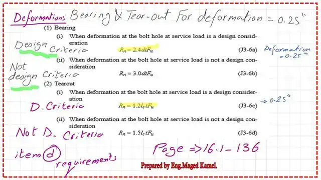
For non-design criteria in the tear-out, Rn = 1.50 × Lc × t × Fu.
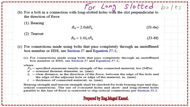
There is a section for the long-slotted, bearing, and tear-out values.
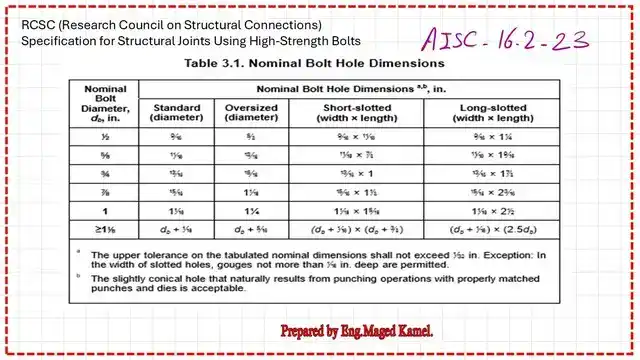
The nominal bolt-hole dimension.
These are the nominal Hole dimensions; for standard dia, we add (1/16″) to evaluate the Hole diameter. There are values for oversized, short-slot, and long-slot.

The same table, but quoted from the Bolt Council for the Nominal Hole Diameter.
The spacing between bolts S is to be taken as 2 2/3*db, and the minimum clear spacing is preferably 3d.
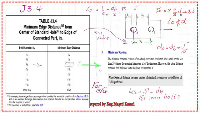
While the internal clear distance between inner bolts should not be <d, the minimum edge distance for the case of Bolt diameter=3/4″ is given in Table J3-4, which is 1 inch.
Solved Problem 10-1: How to get the bearing Value (LRFD) for a connection?
We will start with the second part of problem 10-1, which has been solved. The question is which thickness to consider when estimating bearing. We have two angles and one plate in the bearing case.
We begin by determining the diameter of the Hole and verifying the requirements for inner spacing and external edge distance.

The answer is to select the lowest thickness:: 3/4″ ((the plate thickness)) or the sum of the two angles (2*7/16)=14/16=7/8″. Since 3/4″ < 7/8″, we will select the plate for the bearing calculation.
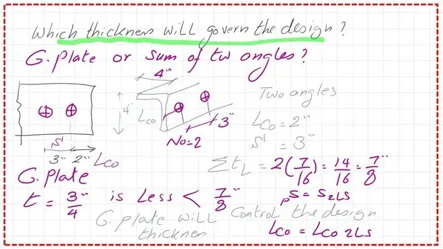
For the edge distance Lc =2 ” -0.50*dh, the hole diameter dh is 3/4 + 1/166 ) =13/16″. lc=2″-0.50*13/16=1.59″>1.
While the internal clear distance = 3″, the clear inner distance = 3″ – (13″/16)=2.1875″, repeated twice, followed by the edge distance.
We consider the plate; this is the appropriate sketch of the Bolt arrangement for a gusset plate. We will List all previous data, including the plate LCO and steel grade. ASTM A-36 for the the plate and angles;; lco and steel grade;; the inner clear distance between bolts;; and the inner clear distance between bolts.
Based on the edge-bolt calculation, the nominal Rnb Value is estimated from the relation (1.2*loc*tpl*Fu).
The Value is estimated at 83 kips. We compare the edge nominal Value with the upper limit, (2.4*d*tp*Fu), which equals 78.30 kips.
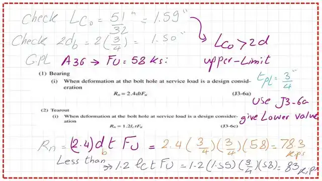
We find that the upper limit is less than the nominal tear-out Value, so it governs the design.
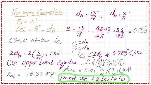
Based on the calculation for the inner bolts, the nominal Value for the inner bolts lt is estimated from the relation (1.2*lic*tpl*Fu). The Value is estimated at 114.21 kips. We compare the edge nominal Value to the upper limit of 78.30 kips.
We find that the upper-limit Value is less than the nominal Value of the inner bolts, so it governs the design.
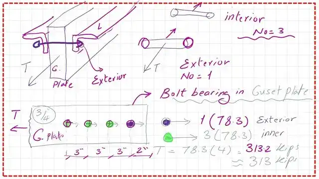
Now, we can see the bearing force values for each Bolt under both LRFD and ASD designs.

Using Table 7-4 for the nominal bearing Value (LRFD) for inner bolts.
Table 7-4 gives the available bearing strength at Bolt holes. The table provides the Value for one Bolt per inch of bearing Area.
The table includes the symbols STD (standard Hole) and SSLPHole (slot), along with other items. The table also shows LRFD and ASD values of 0.75 and 2.00, respectively. We have a table that does not deal with clear distance.
The second column is for Bolt spacing (inner spacing), and it gives two values: 2.2/3*db and 3*db. We have a 3/4″ database, and the Bolt spacing is 3″.
In the third column, there are two Fu values; for the given A36 A36 gusset plate, Fu = 58 ksi. We will select 3″ spacing and Fu = 58 ksi; we draw a line that intersects the line from the 3/4″ column as the nominal Bolt diameter.
We get φRn =78.30 kips/ inch, so we will multiply by gusset plate thickness, which is 3/4″= 78.303/4=58.73 kips for one Bolt, then multiply by 3 inner bolts=3*58.73=176.19 kips.
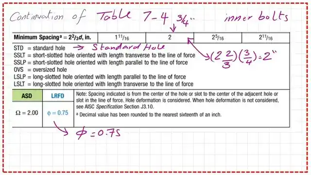

The following slide shows the second part of Table 7-4, which presents bearing values for inner bolts, including LRFD and ASd parameters, as well as the minimum Bolt spacing.
Use Table 7-5 for the nominal bearing Value (LRFD) for external bolts.
The next table is Table 7-5; we will follow the same steps. We have an edge distance of 2″ from the cCL of the external Bolt to the edge. Fu = 58 ksi, db = 3/4″. The intersection will give φ*Rn = 78.30 kips/inch.
Then multiply by 3/4″ for plate thickness by the number of bolts n, which is=1.
φ*Rn=78.3*3/4*1=58.73 kips.The total sum of φ*Rn=235 kips. This matches our previous calculations.

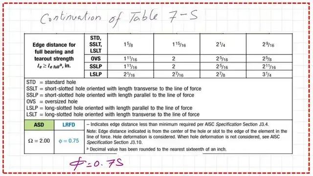
In the next Post, we will estimate the bearing’s ASD and determine which governs the permitted force for the connection. Thank you.
You can view or download the PDF for this Post from the following Link.
You can buy the PDF for solved problem 10-1, which combines posts 5, 6, and 6a, via this Link for just three dollars.
This is a Link to the first part of the same solved problem: How to get the Shear Value?
This is a useful source for designing various Steel elements: A Beginner’s Guide to the Steel Construction Manual, 15th ed., Chapter 4 – Bolted Connections.
This is a useful source for designing various Steel elements: A Beginner’s Guide to the Steel Construction Manual, 16th ed., Chapter 4 – Bolted Connections.
Next post: the Value of bearing-ASD 3-3?