Last Updated on June 18, 2026 by Maged kamel
- A solved problem 10-1-for bearing connection-1-3
- A solved problem 10-1-for bearing connection- How to get the value of shear for a bearing connection?
- A solved problem 10-1- the first method to get Shear strength for a connection by using table J3.2.
- A solved problem 10-1-for-bearing connection- the second method is to get the shear strength for a connection by using Table 7-1.
A solved problem 10-1-for bearing connection-1-3
A solved problem 10-1-for bearing connection- How to get the value of shear for a bearing connection?
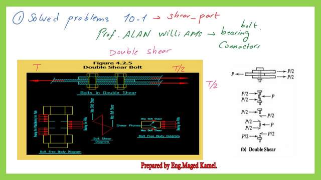
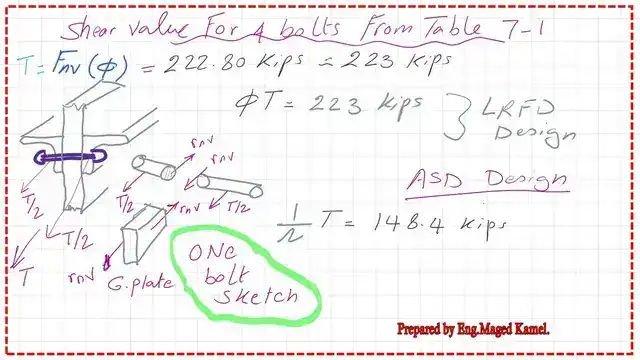
We will review problem 10-1, specifically the shear part, from Prof. Alan Williams’s book. The first part will estimate the shear force applied to a connection based on the shear of bolts. We have a case of double shear. I have included a sketch to illustrate the shear force distribution for the case of double shear, as quoted from the Engineering Beginner site.
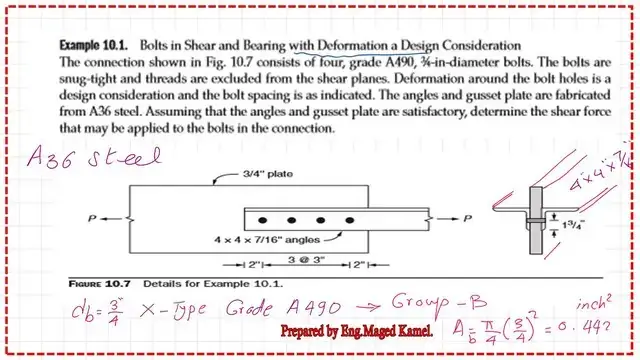
We will start by checking the solved problem 10-1. The title is ‘Bolts in Shear and Bearing with Deformation: A Design Consideration.’ So, the item that we are dealing with is the 0.25″ deformation.
The connection is illustrated in Figure 10.7, which features a double-angle connection with a guest plate. The two angles are Back-to-back and a guest plate; each angle is 4x4x with 7/16″ thickness.
The guest plate is 3/4″ inch thick and Consists of four grade A490,3/4″ diameter bolts. We have four grade A490, Which are type B.3/4″ diameter bolts, with snug-tight, for which bolts are tightened by a spanner, and no pre-tension is done.
The threads are excluded, then the connection is Type B and Type X, from the shear planes. Deformation around the bolt is around is a design criterion or design consideration, and the bolt spacing is as indicated; the inner spacing of bolts is 3″, and the edge distance is 2″.
Assuming that the angles and gusset plate are satisfactory. As I understand, there is no need to check the angle, which is under tension force, against bearing calculations regarding spacing and diameter of bolts.
The only requirement is to determine the shear and bearing for bolts. We will start with God’s will to address the shear stress. The first step is to determine the area of one bolt diameter, 3/4 inch, which is of the Grade A490-X type. The area is equal to 0.442 inch2.
A solved problem 10-1- the first method to get Shear strength for a connection by using table J3.2.
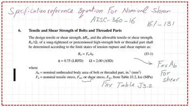
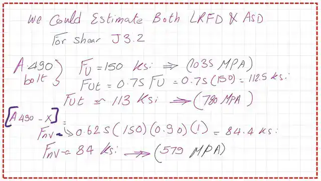
We have two methods to evaluate the nominal shear strength; the first one is by using Table J-3.2. the next slide show the AisC-360-16 provision for the equation used to get the Nominal shear value.
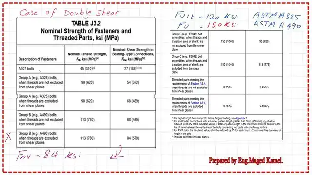
We have Table J.3.2 for the A solved problem 10-1-forbearing connection, which we included in the last video. Let us review our given data. We have bolts that are classified as being in group B with ASTM-A-490 and Are Excluded.
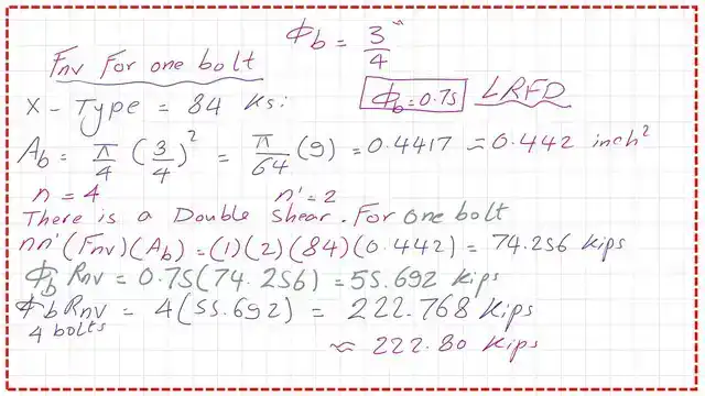
Then multiply ( 2 Fnv) by the number of bolts by the area of each bolt. We get the value of Rnv, which is equal to 297.02 kips. To get the design nominal shear strength multiplied by the phi value, which is 0.75. The LRFd value of shear strength is 222.8 kips.
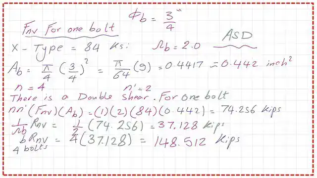
For the ASD shear strength value, multiply Rnv by (1/ omega). The omega value is 2. The ASD value is 148.152 kips. Please refer to the next slide image for more details.
Our case is the fourth item, as shown in the table. We have the highest nominal shear value of 84 ksi. This value is for single shear; we will multiply by two for the case of double shear.
A solved problem 10-1-for-bearing connection- the second method is to get the shear strength for a connection by using Table 7-1.
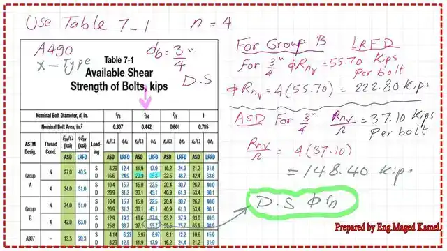
Table 7-1 gives the shear Fnv value for both LRFD and ASD, based on bolt diameter. For our solved problem 10-1, we have a 3/4-inch bolt group B Type-x.
The φ*Rnv for a double shear bolt is 55.70 kips per bolt, which we will multiply by the number of bolts, which is 4. The design shear strength is 222.80 kips, which matches the previous estimate from Table J3-2.
The (1/Ω)*Rnv for a double shear bolt is 37.10 kips per bolt, which we will multiply by the number of bolts, which is 4. The ASD design shear strength is equal to 148.40 kips, which matches the previous estimate based on Table J3-2.
A sketch shows the shear force distribution for both LRFD and ASD design values. The direction of shear force is opposite to the direction of the applied force.
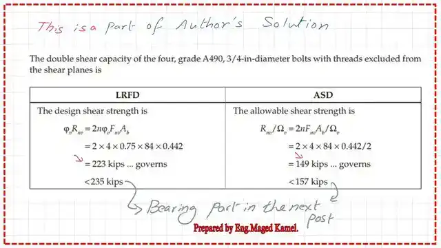
The figures shown are the shear values for the connection in solved problem 10-1, as quoted from the author’s book.
This is the pdf file for the content of this post.
This is a very useful source for the design of various Steel elements, A Beginner’s Guide to the Steel Construction Manual, 15th ed, Chapter 4 – Bolted Connections.
This is a very useful source for the design of various Steel elements, A Beginner’s Guide to the Steel Construction Manual, 16th ed, Chapter 4 – Bolted Connections.
The next post post 6, is solved problem 10-1-how to get Bearing value-LRFD-2-3