
Last Updated on March 14, 2026 by Maged kamel
- Bearing Type connections-part-2.
- Summary of the post content.
- The nominal tensile strength for a bolt Rn.
- AISC equations for bearing connections.
- Minimum edge distance of bolts Tables J3.4 and J3.4M.
- Minimum Spacing S and the inner distance between bolts.
- Nominal hole dimension for bearing type connection.
- The nominal strength of fasteners.
Bearing Type connections-part-2.
Summary of the post content.

The nominal tensile strength for a bolt Rn.
In this post-bearing Type connections-part-2. The distance le is the edge distance from the centerline of the bolt to the edge.
We are concerned with the distance behind the bolt (Le-d/2), where le is the distance from the Cg of the external bolt to the adjacent edge. At the same time, d is (the diameter of the bolt+1/16″).
The clear distance is called lc outer Lco, which is the distance from the edge of the external bolt to the edge of the plate. This is the section of the two connected plates on the following slide.
Rn is the nominal bearing force due to the application of a tension force at the left; Rn is the sum of the two forces at each side of line 1-1 and line 2-2 and can be estimated as equal to 2*0.6Fu*Lco*tp since the shear strength is calculated as equals 0.60Fu. The length of each side equals lco, and the height of the plate equals t.

If the surrounding material is weak, the bolt will be stronger than the surrounding material due to tearing the shear plane. What will happen? Two forces will resist the Tear-out, the sum of these forces equal to 1.2*Fu*tpl*Lo, where Lo is the clear distance from the edge of the bolt.

We will examine the inner distance between two bolts. The nominal force R is split into R/2 and R/2. The shear strength of the plate’s material =lc*t*0.60 Fu.
The value of Resistance is the lower limit if Lco is less than 2d.
The upper limit is achieved when lc=2d—the nominal resistance equals 2*0.60*Fu*2d*t*2=2.4*Fu*t*Lco.

AISC equations for bearing connections.
For the next slide, a series of equations Rn= 1.20*Lc*t*Fu.< or =2.40*d*t*Fu, if deformation around bolt holes is a design consideration if the deformation is less or equal to 0.25 inches. The value of (1.20*Lc*t*Fu) is reached when lc is less than 2dh.
The ubber limit value of (2.40*d*t*Fu) is reached when lc equals 2dh.
But if the deformation is>0.25 inches and is not a design consideration, then Rn= 1.50*Fu*Lc*t <= 3.0*d*t*Fu. There is another condition for long slotted holes.

In the next slide, refer to the definitions. The distance between the centerline of bolts in the direction parallel to the axis of the member is the pitch P. S is the gage distance, which is the distance between the centerline of bolts in the direction perpendicular to the axis of the member and the edge distance.

Minimum edge distance of bolts Tables J3.4 and J3.4M.
In the next slide, the minimum edge distance varies according to the diameter of the bolts and follows the Table shown in J3.4. The metric version of the same table, J3.4M, is also included.
If we have a bolt diameter of 3/4 inch, the minimum edge distance is equal to 1 inch. For the metric dimension, a bolt of dia 20mm will have a minimum edge distance equal to 20mm, as shown in Table J3.4M.

The minimum external for oversized or slotted holes equals le plus c2, where the value iof C2 is obtained from tavle J3.5.

Minimum Spacing S and the inner distance between bolts.
In the post-Bearing Type connections-part-2.The minimum spacing between bolts is S.
The minimum center-to-centerline distance is not less than (2 2/3 db), where db is the bolt diameter. Preferably, it should be 3d as 3 diameters. But the clear distance should be not less than d.
Minimum Center to Center should be not less than 2 2/3 diameter.

The following slide image shows the different types of holes. Oversized holes are used in slip-critical connections, while short slotted holes can be used for slip-critical and snug-tight connections. The long slotted can be used for slip-critical and snug-tight connections.

Nominal hole dimension for bearing type connection.
For the hole diameter, add 1/16″ to the bolt diameter, unlike in tension members we were adding (1/16″+1/16″) to the bolt diameter For the calculations. For instance, for a 3/4 ” diameter bolt add 1/16″, then the standard dia will be (3/4+1/16)=13/16″ as shown in table J3.3. The table gives the different hole dimensions as four standard oversized short and long slots. There is a sketch for the various types of holes, please refer to teh next slide image.

The nominal strength of fasteners.
In the next slide, the value of shear strength is shown in Table J3.2.
The tensile strength, written as Fnt, is in the second column. The nominal shear strength symbol, Fnv, is in the third column, and it is a percentage of Fnt.
For instance. In the first column, there is a description of the type of fasteners, A307, Group A A325-N which are not excluded, the tensile strengthFnt=90 ksi, and the Fnv=0.60*90=54 Ksi, the value shown between brackets is the Mpa value, for A325-X, Fnt=90 ksi. Fnv=68 ksi. For the case of X the shear strength increased, there are categories b) as ASTM-A490 bolts N&X with the corresponding Fnt and Fnv values are shown.
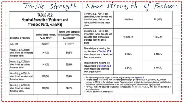
The shear strength increased for X. Category b) shows ASTM-A490 bolts N&X with the corresponding Fnt and Fnv values.
The following Table J3.5 and J3.5M show the required values for C2.

The last slide image is quoted from the specification for the maximum spacing and edge distance. The maximum spacing from any bolt to the nearest edge shall not be more than 12 times the thickness of the connected part but shall not exceed 6 inches.

This is the PDF file used for this post.
For part 1-bearing type connection-part-1, this is the link.
The next post is about nominal shear strength and bearing tear-out made simple.
This is a very useful source for the design of various Steel elements, A Beginner’s Guide to the Steel Construction Manual, 15th ed, Chapter 4 – Bolted Connections.
This is a very useful source for the design of various Steel elements, A Beginner’s Guide to the Steel Construction Manual, 16th ed, Chapter 4 – Bolted Connections.