
Last Updated on January 23, 2026 by Maged kamel
How to use the Newton-Raphson method for structural analysis?
The Newton-Raphson method can be used to perform a structural analysis of a simply supported beam under a uniformly distributed load to determine its maximum deflection. Two approaches will be used. The first approach is by using the Newton-Raphson method.
The second approach will use the modified Newton-Raphson method.
Revisit the Newton-Raphson method-The first approach.
First, we have the y-axis which is located at the left support point, Then we select point A which is apart from the Y-axis by a distance X0, and we make a slope at that point A, shown on the graph of f(x), that slope will intersect with the x-axis at a certain point which will have a horizontal distance of X1 from the y- axis.
Then we will either measure or calculate the corresponding value of Y, or f(x1), for that point.
We repeat the process from point B, we get another point B’, the second step is we are going to make a slope at point B’, and then the slope will hit the X-axis again at a certain point, for that new point we call it point C.
We are looking for the point with a y-value of 0. We estimate the Y value, and so on; we are taking several steps, which is why we are approaching the root of the Y value.
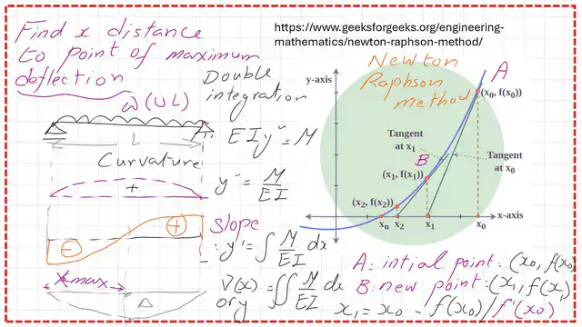
The point of maximum deflection for a beam under uniform loading.
As a direct application of this method, for a uniformly distributed load, for example, after structural analysis, we obtain a deflection curve and identify the point of maximum deflection, which corresponds to the X coordinate of the left support.
Here for that curvature for the deflection, we don’t have an intersection for the deflection curve with the X-axis except for x=0 or X =L, that’s why we cannot directly use the Newton-Raphson method by that expression of X1= x0-(f(x0)/f'(x0) to get the distance to the point of maximum deflection.
We use the beam’s slope graph to apply the Newton-Raphson method.
The slope at the maximum point of deflection will be 0, or the curve of slope intersects the X-axis. That’s why, while checking the slope, y’ curve, we find that the point of zero, or the root point, has the same distance, Xmax, from the left support.
Thus, the idea is to utilise the y’ curve as the primary curve to perform a structural analysis of a beam and determine the distance to the maximum deflection.
In the next slide, we will see a graph for the expression of Newton-Raphson x1=x0-f(x0)/f'(x0), which deals with Y as an f(x) when the Y curve intersects with the x-axis.
But in our case, the Y’ curve is the one that intersects with the x-axis. Now our root point is at another curve, which is y’, the slope curve for the uniformly distributed load on a simply supported beam, which is a function of X’.
Accordingly, the Newton-Raphson method’s terms will be modified, as shown in the next slide. Based on the Newton-Raphson Method, x1=x0-f(x0)/f'(x0), while we were dealing with Y as a function of X.
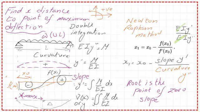
Now our root point is at another curve, which is y’, that’s why we are going to replace the original expression, for instance, f(x0), with f ‘(x0) and f'(x0) value by f”(x0).
The double integration method expression or elastic curve is y”=M/EI, while y’ is the slope, and it can be calculated by the integration of M/EI. The expression for y, which is the deflection value, is given by double integration of M/ EI.
Let us see how we can proceed using the y’-slope curve.
First, select the X0 distance arbitrarily chosen, this is your starting point, the slope from the left-hand side is negative, so we will estimate the f'(x0).
This time we draw a curve. We draw a slope at that point, then we hit the y’ curve by another new point, which is apart from x1. The same procedure we have done earlier, for that x1, we are going to estimate y’ of x1 point for the f”(x0), we will proceed to the curve of y”, and we get the corresponding f”(x0).
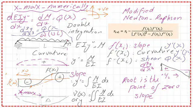
Using the Modified Newton-Raphson method.
As a second approach using the modified Newton-Raphson method for the structural analysis, the expression of the equation will be modified as:
Replace f(x) by f'(x), and f'(x) by f”(x). How are we going to get f”‘(xi)? By recalling the expression that y”, which is a curvature variation, is =M/EI, when you are going to make differentiation for d2v/dx2, accordingly, you will make differentiation for M/EI, so for d3V/dx3= (dM/dx)/ y/EI, expression. We are familiar with the dM/dX, which is the shear diagram; that’s why d3v/dx3 = Q/Ei.
A practice problem, a beam under a concentrated load.
I have added a new practice problem to illustrate the idea. Rather than using a beam with a uniform load, since we know already that the maximum deflection point is located at the middle. I selected a beam with a point load, as we will see next. Based on the analytic solution, using Macaulay’s function, the distance to the point of maximum deflection is 8.165m from the left support.

The expressions for load, shear, moment slope, and deflection are discontinuity functions.
In the following slide, we can see the details of the load, shear moment, slope, and deflection expressions for the given beam. But it is important to note that for the region between a and b, we do not use the expressions marked in green, as they are valid only for x>10m.

The maximum value is 400 kN · m at a distance of 10m from the left support. For the value of EI, it is equal to 14*10^4 KN · m^2.

The following slides show the graph for slope and deflection values for the given beam.


Use the Newton-Raphson method to get the point of Maximum deflection.
As I have indicated, we will use the EI*v’, or the slope function as f(x) in the Newton-Raphson method, and the f'(x) function will be the EIV” which is the Moment M(x) of the beam. Our initial guess is X0=4.00m, the point of the maximum moment is between A and B, so we do not use the expression for (x-10).
The value of x1=x0-(EIV'(X0=4.00)/EIV”(X0=4)). We get the estimated values for EIV’ and EIV” for x0=4 m and substitute; we get X1 = 10.3333 m, which is greater than 10.0 m.

The following slide shows the estimation of EIV’ and EIV’ values for X1=10.333 m. We will use the full expression since x > 10 m, and we will find that x2 = 8.2381 m.

The value of X3 is found to be 8.165m, which is exactly the figure obtained by the analytical method.

A table for the different values of xi starting from x0=4.00 m till X4=8.165 m, based on the Newton-Raphson method.

Use the modified Newton-Raphson method to get the point of Maximum deflection.
In the following slide, we can see the details of the load, shear moment, slope, and deflection expressions for the given beam. But it is important to note that for the region between a and b, we do not use the expressions marked in green, as they are valid only for x>10m. The shear V(x) is expressed as EIV”‘.

We will start with an initial value of x0 = 4.0 m, but to apply the Modified Newton-Raphson equation, we need to find the shear Value Q(x) as EIV”‘, EIV’ as F(x), and EIV” as M(x). The value of X1=6.4516 m.We will use an Excel sheet to find the various values of Xi.

This is the last slide for estimating Xi using the modified Newton-Raphson method to find the point of Maximum deflection, for x4, the value equals 8.165 m. Thanks a lot.

The data for this post can be reviewed or downloaded from the following link.
The next post will include a solved problem for the application of this method. The next post link is the Maximum deflection distance by the Newton-Raphson method.
This is a useful link for a numerical analysis calculator.