
Last Updated on September 15, 2026 by Maged kamel
Moment Redistribution For Continuous Steel Beams.
Elastic redistribution for Moment values.
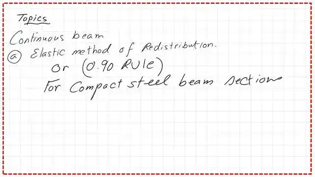
The design of continuous beams is a new subject. The first method is the elastic method of Moment redistribution, also known as the 0.90 rule. We will introduce different types of beams with continuous spans and fixed end moments. We will compare the Moment values before and after redistribution.
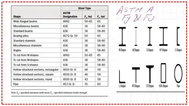
Let us look at W-shapes, M-shapes, S-shapes, Hp-shapes, and c-shapes; L-shapes; wt-shapes; HSS-shapes; and pipe-shapes, along with the ASTM designation and the values of both Fy and Fult for each shape. For instance, for a wide-flange Beam, Fy = 50- 65 ksi is based on A992 steel, and for hollow structural sections, it is rectangular, Fy = 46 ksi.
This is a brief revision of the Fy and Fult values for different ASTM types.
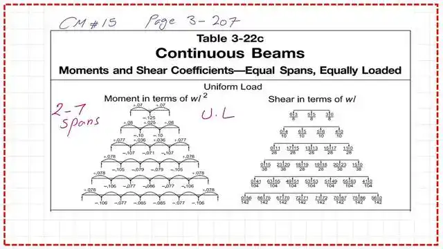
The following image shows the Shear and Moment values of the continuous beams with three equal spans under a uniformly distributed Load.

Refer to Table 3-22c for different types of continuous spans, from 2 to 7 spans, and the corresponding Shear and Moment values under a distributed Load.
Code requirements for Moment redistribution.
The AISC code permits utilizing this Moment by redistributing it. Chapter B of the specification shows this procedure under clause B3.3. Please refer to the following slide images for more details.
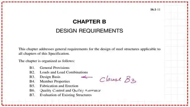
The structural analysis for the applicable Load combination shall determine the required strength of the structural members and connections, in accordance with section B2.
As we will see later, we can deduct 10% from the negative Moment and add it to the positive Moment, depending on the position of the maximum Moment. The required yield stress is not to exceed 65 ksi.

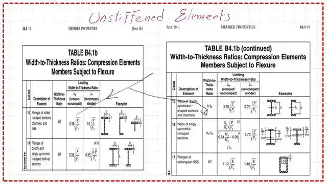
The clause states that the steel section of the Beam must be compact, in accordance with the requirements of Section B4. Please refer to the following slide for the unstiffened and stiffened sections and their lambda p values.
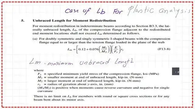
Clause 5: unbraced length for Moment redistribution.

The following slides show the data for clause F13-5 of the Lm requirement, which specifies the distance between bracings to allow for Moment redistribution.
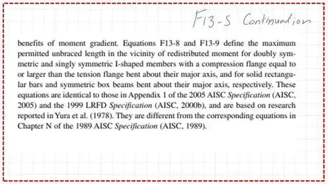
The AISC has stated that the length between bracing should not exceed lm to allow redistribution. Most solved problems assume the Beam has continuous bracing. In the Appendix on plastic analysis and design, Professor Segui discusses the F13-8 formula by presenting a solved problem (A-2).
The next slide shows the details of the F13-8 equation for the Lm Value.
How do we perform redistribution?
We will consider a continuous Beam with two equal spans, with a uniform Load. The following slide image shows the Moment values before and after redistribution.

The maximum bending Moment is 0.125 wl2, which is greater than the positive Value of 0.07 wl2. We deduct 10% from the negative Value, so the final Value is 9/80 wl2.

We add 0.5 of 0.1*0.125 Wl^2, since the maximum Moment occurs at the midpoint of the first span. The final positive Value equals 0.07625 Wl^2. Please refer to the slide image below.
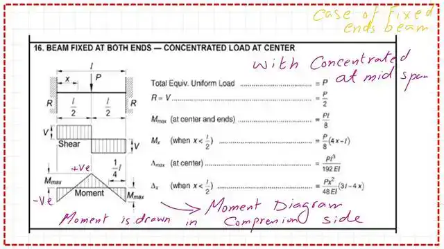
Elastic Moment distribution for a fixed-end Beam with a central Load.
We will now review fixed-end moments in a one-span Beam with a central point Load. This sketch shows the fixed-end Beam’s Shear and bending Moment values.
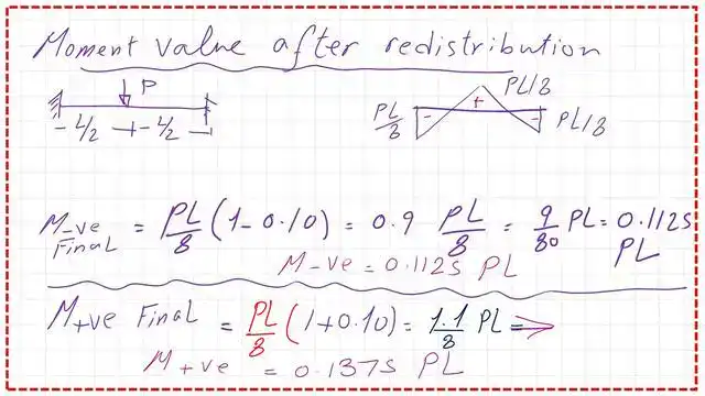
The positive and negative Moment values are the same, equal to wl^2/8. The final negative Moment is 0.1125 PL, and the final positive Moment is 0.1375 PL.
The following image shows the Shear and Moment values for a fixed-end Beam under a uniformly distributed Load.
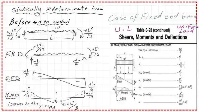
Elastic Moment distribution for a fixed-end Beam with a uniform Load.
Deduct 10% of the fixed-end Moment Value; the final fixed-end Moment will be 3*WL^2/40.
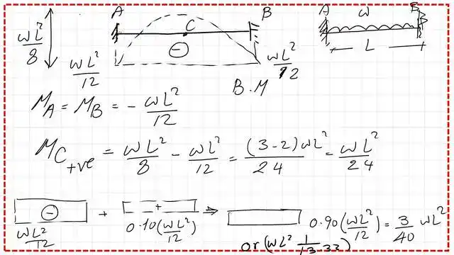

The positive bending Moment before redistribution is equal to 0.07 WL^2. After redistribution, the Moment will increase by 0.10*(w*L2)/12 = 0.00833 WL2. The slide image shows the Moment’s Value after using the 0.90 rule.
You can view or download the PDF for this Post from the following Link.
The next post, 30, solves Problem 4-15. It includes instructions for designing a two-span continuous Beam and is considered an application of Moment redistribution.
Here is the Link to Chapter 8 – Bending Members, section, A Beginner’s Guide to the Steel Construction Manual, 14th ed.
Here is the Link to Chapter 8 – Bending Members, section, A Beginner’s Guide to the Steel Construction Manual, 15th ed.
Here is the Link to Chapter 8 – Bending Members, section, A Beginner’s Guide to the Steel Construction Manual, 16th ed.