Last Updated on April 8, 2025 by Maged kamel
Introduction To Block Shear Resistance.
This is the content of the lecture.

Slenderness ratio as recommended by Aisc.
The first part includes the recommendation of the slenderness ratio L/r from the code, which is preferred to be =300 due to handling and controlling vibration effects.
Handling very slender sections is problematic; the main requirement is to hold without inadvertent bending.
Lifting a slender section by crane might buckle or be distorted due to transportation and erection. Experience has shown that if you limit the slenderness L/r to 300,
You are less likely to have problems handling the member with the experience if we deal with a slenderness ratio L/r at a value of 300.
The problems that will occur during handling can be minimized; there is not a strength limit state, the limit state is the same for both LRFD and ASD, and L/r is not related to LRFD or ASD parameters.
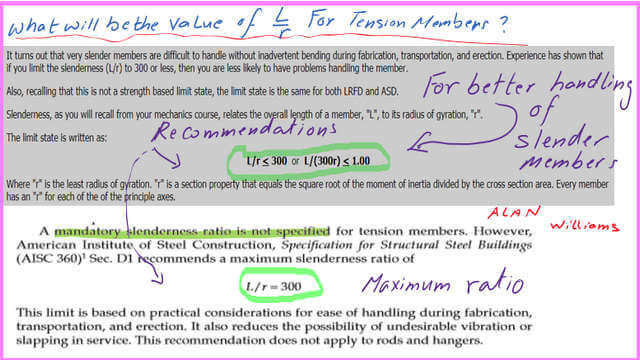
The code recommendation is in chapter D. Design of Members for Tension, specification 16.1—page 28, AISC 360.
In Chapter D1, the slenderness ratio L/r for members designed based on tension should preferably not exceed 300. This suggestion does not apply to rods or hangers in tension.

How do we derive the equation for block shear for tension members?
If bolts join two pieces, they are subjected to two equal and opposing tensile forces.
After studying one section, we will discover that the tensile force may be divided into two components: one is perpendicular to part bc, as shown in the illustration.
In contrast, the other component generates shear in part ab. There will be two types of fractures: yielding and rupture for tension and shear stresses.

The failure does not extend to the upper part of the angle since it is considered a stiffened end.
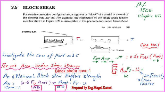
Block shear Formula.
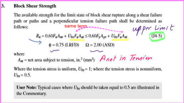
This is the nominal value Rn calculated using the formula, which has two parts: one for shear and one for tension.
The expression for Area Agv is the gross area with a shear component, and we do not deduct the bolt area. While Ant is the net area with a tensile component, from which we deduct the bolt area. The stress for shear is taken as 0.60 times the tension stress.
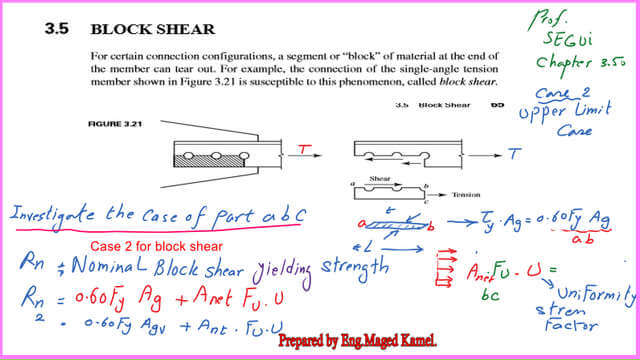
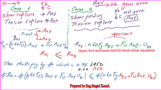
The difference between the upper limit and the lower limit.
The difference between the upper limit of fracture and the other limit of failure will be considered as follows: The upper limit of fracture combines Tension failure by rupture and shear failure by yielding.
The shear fracture term is the product of Anv x0.60Fu, while the shear yielding term is the product of Agv x0.60FU.
The tension rupture term is the product of Ant by Ubs by Fult. This term is common between the lower and the upper bound.
For the LRFD design, we multiply the maximum value of the two cases by phi, which equals 0.75. For the ASD design, we multiply the maximum value of the two cases by (1/omega), and Omega equals 2.
UBS values vary based on the uniformity of stress distribution for angles and guest plates. Most coped beams have a uniform stress distribution. The second case is where Ubs=0.50 for a nonuniform stress distribution. The UBS values are shown in the next slide image.

The next slide is the reference in the specs for Chapter J, which concerns connections. The specification provides for steel connections.
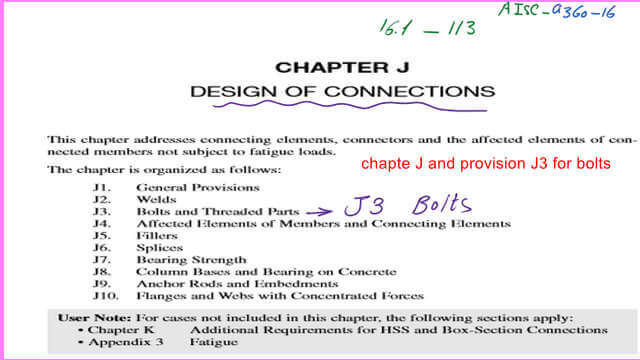
In the next slide, the equation for the block shear strength is J4.5.
There is a very useful external link, Shear Rupture–
The following post is a Solved problem 4-4, How to get Pult without block shear.