
Last Updated on February 23, 2026 by Maged kamel
- Nominal shear strength and bearing- tear out for bearing connections.
- The nominal shear strength for a bolt Fnv.
- What is the Tensile stress and Shear strength of the A307 Bolt?
- What is the Tensile stress and Shear strength of the A325 Bolt?
- What is the Tensile stress and Shear strength of the A490 Bolt?
- Table J-2-Nominal shear strength of Fastners.
- The values of nominal shear strength and nominal tensile strength for bolts in the RCSC.
- Bearing and tear -out of a simple connection- A Tale of tearouts.
Nominal shear strength and bearing- tear out for bearing connections.
The post content has two items. The first is the relation between ultimate stress and nominal shear strength, while the second is the description of bearing and tear-out. These items are shown in the next slide image.

The nominal shear strength for a bolt Fnv.
The Nominal shear strength denoted as Fnv is based on Ultimate strength. The relation stated that Fnv=Fult* 0.625. We previously discussed the shear subject while discussing the shear for beams, and we consider the shear stress factor to be approximately 0.60.
However, regarding the bolts, the Code considers that the Nominal strength =Fu*0.625, again multiplied by two factors. The first factor is Ca, and Ca depends on the length of the connection. If the connection length is = 38 inches, Ca equals 0.90; otherwise, it will equal 0.75.
Meanwhile, Cb is for the types of threaded, whether included or excluded, for high-strength tensile bolts, whether X or N.

For the case of Ca, it is equal to 0.75 if the connection is bigger than 38″. Ca is equal to 0.90 if the connection is =38″. For the case of Cb, it is equal to 1 if the threaded part is excluded or the shear line does not pass by the bolt’s thread. It is equal to 0.80 if the threaded is included, which means that the shear plane cuts the threaded portion of bolts.
What is the Tensile stress and Shear strength of the A307 Bolt?
Bolt A307 is A carbon steel Bolt ranging from 1/4 inch to 4 inches in diameter.

In the next slide image, there is a detailed estimate of the tensile stress and shear strength of A307 bolts.

What is the Tensile stress and Shear strength of the A325 Bolt?
Let us refer back to the equation: the shear if Fult = 120 ksi. while the shear factor 0.625*ca=0.90 if the connection is >38″, cb=1 for threaded portion is excluded, the multiplication will give =120*0.625*0.9*1=67.50 KSI.

However, if we consider the threaded inclusion, we multiply again by 0.80, resulting in 67.5 × 0.80 = 54 ksi.
What is the Tensile stress and Shear strength of the A490 Bolt?
For group A, ASTM A 490, Fult=150.0 ksi, the tensile stress Fut and shear stress Fnv is shown in the next slide image.

Table J-2-Nominal shear strength of Fastners.
Table J3.2 is divided into two parts: nominal tensile strength Fut= 0.75*Fult, whether threaded included or excluded.
For group C, where ASTM F-3043, the tensile stress Fnt=0.75*200=150 ksi. Please refer to the next slide image of Table J3.2.

The values of nominal shear strength and nominal tensile strength for bolts in the RCSC.
Refer to the bolt council table, Research Council on Structural Connections. For ASTM A 325 or group A, the static tension is 90 ksi. The static tension in group B is 113 ksi. For fatigue due to repeated loads, such as in bridges, refer to Section 5.5.
Here is the shear condition for connection = 38″: We will have fnv=68 ksi and 54 Ksi; refer back to table J3.2. The exact figures are there. If the connection is >38″, then Fnv will be 45 ksi and 56 ksi for the threaded included in the shear plane.
Here, in the case of threaded is excluded, the first case for connection <=38″, we have Fnv=68 ksi and 84 ksi. Back to J3.2, we will find the two figures Fnv =68 ksi and 84 ksi. The case for the included thread with connection>38″.
Again, for group B, Fult=150 ksi multiplied by 0.625*0.90*1=84 ksi will give Fnv for the x condition, where threads are not included. For the N condition, where threads are included, then Fnv=150*0.563*0.80=67.50=68 ksi.

For the bearing and tear out, LRFD and ASD values φ=0.75 while Ω=2.00 for the nominal strength of the connected material.

The different equations presented in the specifications are provided below. For case ( i ) of bearing, when elongation of 0.25″ is a design criterion, then Rn=2.40*d*t*Fult.
For case ii of bearing, when elongation of 0.25″ is not a design criterion, a higher value for Rn is given, Rn=3*d*t*Fult.
For the tear-out case( i), if deformation at the bolt hole is a design criterion, Rn=1.2LctFult, Rn=1.5Let*Fult if the deformation is not a design criterion.

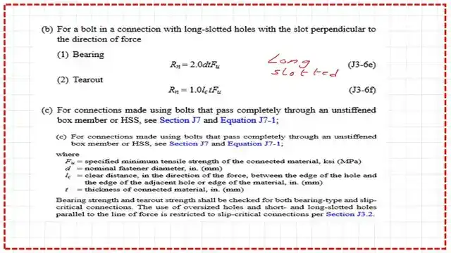
For long slotted connection with the slot perpendicular to the direction of the force. Again, the bearing value is Rn=2.30dtfult, while for tear-out Rn=1.0LcFultt, there is a condition c for connections made using bolts that pass entirely through an un-stiffened box member.
This is table J3.3 if the bolt gives the hole dimension for various bolt values, whether it is an oversized, short slot, or long slot. The hole diameter is bigger than the diameter of the bolt by 1/16″ for the standard, as shown in the table.
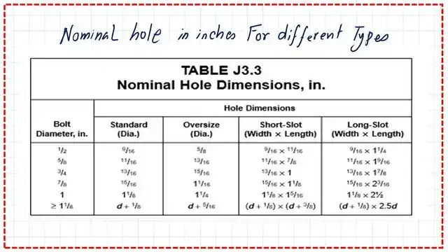
Table 3.1 contains nominal bolt hole dimensions for standard diameter, oversized, shot slotted, or long slotted bolts. The bearing value is based on the slot condition.

Table J3.4, introduced earlier, determines the minimum edge distance from the bolt’s centerline.

Bearing and tear -out of a simple connection- A Tale of tearouts.
The following images are quoted from the specs and include crucial information about Tear Out.
Then, a discussion of the tear-out is shown. The tear-out for Lh external: One part will split the same as a wedge shape. The inclination angle is based on the external clear distance.

Bearing depends on the hole elongation. This is different from the slip connection, which we will discuss later. On the critical slip, elongation is prevented. I quote when deformation at the hole elongation will not exceed 1/4″. When high tensile stress occurs on the net section, other relations can be estimated if it is not a design criterion.

If not a design criterion, then Rn=1.5*Lc*t* Fult. Again, this is a slide for tear-out for the Rn value.
The change is that the values of Rn changed between specifications 2010 and 2016: Rn upper value = 2.4dtFult and Rn = 1.2lct*Fult.If the deformation is of design criteria, or deformation 0.25″ or not, then the equation is to check out the upper limit, which is 2.4*d *t*Fult.


This is a link to download A Tale of Tearouts from Specwise. It contains an interesting solved problem for a connection and how to determine the shear bearing values.
This is the pdf file for the content of this post.
This is a very useful source for the design of various Steel elements, A Beginner’s Guide to the Steel Construction Manual, 15th ed, Chapter 4 – Bolted Connections.
This is a very useful source for the design of various Steel elements, A Beginner’s Guide to the Steel Construction Manual, 16th ed, Chapter 4 – Bolted Connections.
The following post presents the solution to problem 10-1 for the shear force value.