Last Updated on December 7, 2025 by Maged kamel
Plastic Nominal Uniform load for partially loaded beam.
We will adjust the solved problem in the previous post by making the uniform load occupy half the length of the span but from the left side.
For the steel beam with a section of W18x40 and a yield strength Fy=50 ksi, the Plastic Nominal Uniform load for the partially loaded beam, Wn Value, must be estimated.
What is the distance x for a point of maximum moment?
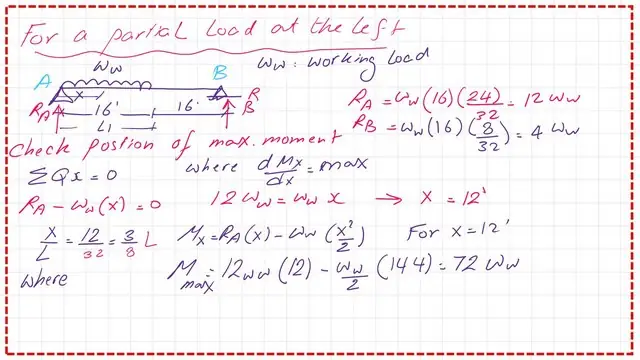
In the case of working load w, we can find the position of the point of maximum moment by using the summation of shear forces to be equal to zero.
First, we estimate the reaction at A and at B. RA value equals 12w, where w is the working uniform load. Similarly, Rb will be equal to 6w
If x is, the distance from the left support to the point of the maximum moment, its value will be equal to RA/w =12 feet. The value of the maximum moment will be equal to 72 w. Please refer to the next slide image for more information.

Solving the modified example by the lower bound theorem.
when w is equal to the nominal load Wn, the maximum moment will be equal to Mnand we can equate the Mn to 72*wn. We have a given section of W18x40, use a table to get Zx, the plastic section modulus for that section, Zx value=78.40 inch3. The yield stress is 50 ksi.
The Nominal Mn= Mp=Fy*Zx=50*78.40 inch. kips, We have Mn=326.66DFt kips, so the nominal load wn is equal to 4.537 Kips/Ft. Please refer to the next slide image for more details.

Solving problem 8-32 using the upper bound theorem.
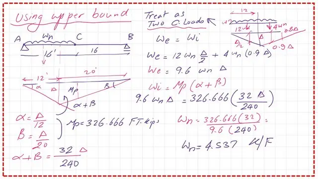
For the same modified problem, to estimate the Plastic Nominal Uniform load for a partially loaded beam, we will create a mechanism, and the same procedure will be followed.
Partial loading can be considered the sum of two cases: the first case, where the span is under full load acting downwards, minus the case where partial loads act upwards.
The plastic hinge is located at the place of the maximum moment at x=12′ from the left support.
The deflection at that point is Δ, the angle at A due to that deflection=θ, and the angle at support B is θ1.
The internal work=Mp*(θ+θ1). θ=tan θ=Δ/12, while θ1=tan θ1=Δ/20.
For the external work=We1=0.50*Wn*32*Δ, then We=32*Wn/2-We2, we will estimate the deflection value at the edge, which has a distance of 16′ from support B, The value of Δc can be estimated from Δc/Δ=16/20, Δc=0.80*Δ.
We estimate the average for the deflection at point C, Δc, which is 0.40*Δ. The value of We=Wn*Δ*16-Wn*16*0.40*Δ, We=16*Wn(1-0.40)=9.6*Wn*Δ.
For the internal work Wi=Mp*(θ+θ1), θ+θ1=(Δ/12)+(Δ/20)=32*Δ/240.
We=9.60*Wn*Δ)=Mp*32*Δ/240. Wn=32Mp/(2409.60), Wn=32326.66/(2409.60)=4.54 kips/ft. We can find the value of the Plastic Nominal Uniform load is equal to 4.54 kips/ft.

We get the same value of 4.54 kps/ft as the Plastic Nominal Uniform load for the partially loaded beam from both the lower and upper bound methods, which are identical.
Solving the modified example by MASTAN 2.
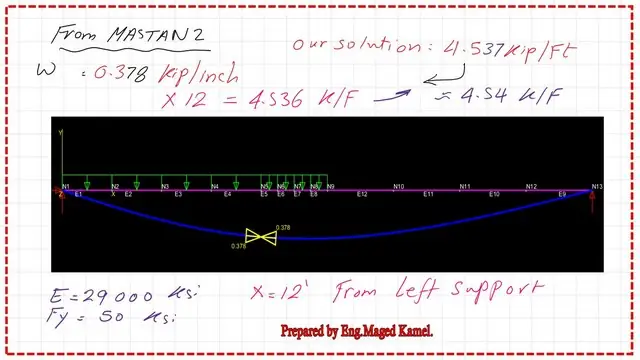
The partially loaded beam under a uniform load has been solved by Mastan-2 using 1.0 kips/inch and using increments, but at a load equal to 0.378 kips/inch, a plastic hinge is formed at 144 inches from the left support.
The value of 0.378 kip/inch matches our solution of 4.54 kips/ft. The deflected shape of the beam is shown in the next slide image, together with the location of the plastic hinge.

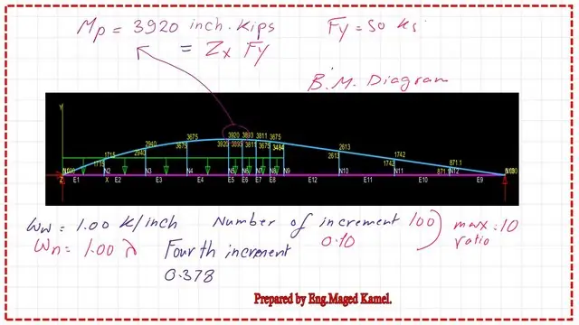
In the next slide, we can see the Bending moment diagram for the partially loaded beam, and we note that the Plastic moment value is 3920 inch. kips, which is 326.66 ft. kips, and the nominal load is 4.537 kips /ft.

Have more information about the structural analysis –III.
The next post is Solved problems 8-33&34 for a nominal uniform load.