Last Updated on November 24, 2025 by Maged kamel
Solved problem 4-14 part 2 for the effective length factor.
Estimate GB value for joint B of the column.
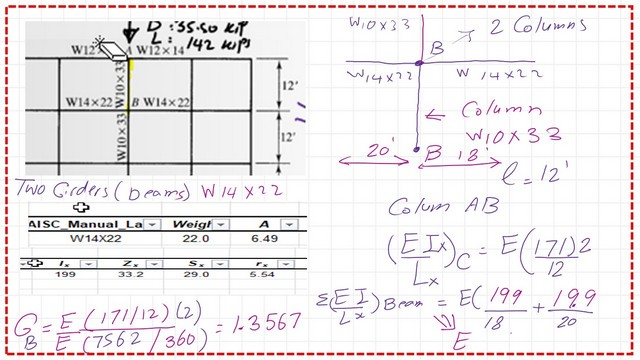
At joint B, two columns will be considered. For each column section, W10x33, we have two beams with section W14x. For each, we estimated the area of the beam section as Ag = 6.49 in², Ix = 199 in⁴, and rx = 5.54 in². The inertia of the column is < inertia of the two beams.
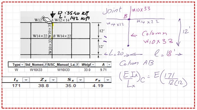
Gb value equals 2∑EI/L for column AB /∑EI/L for the two framing beams. The terms E for column and E for beams will cancel each other; the numerator =Ix/L for column equals 2(171/12).
The denominator equals ∑EI/L for beams, which will be the sum of two items. The first item equals (I/L) for beam1, which has a length of 18 ft, while the second beam has a length of 20 ft.
The two beams have an inertia of 199.0 inch4. The sum is (199/20 + 199/18). The Gb value will be equal to 1.3567; please refer to the next slide image.
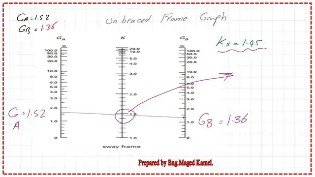
Use the alignment chart to get the K value for column AB.
Since we have unbraced frames, we can use the unbraced frame graph to get the K factor using the estimated GA and GB. We can find that the effective length k value is equal to 1.45.
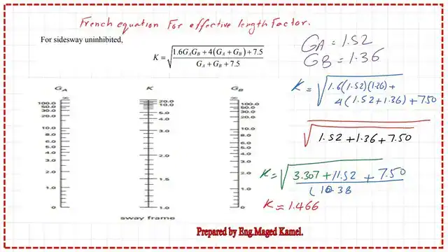
To use the French equation, we substitute the different values, and we obtain k = SQRT (1.60GAGb + 4 (GA + GB) + 7.50)/SQRT(GA + GB + 7.50), which yields k = 1.466.
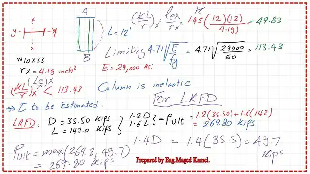
Having estimated the k value, check that K*L/r is smaller or bigger than 4.71*Sqrt(E/Fy).
We proceed, having k=1.45, then KL/r at x=1.45(1212)/rx of the column which=4.19 inch2, KL/r at x=49.83.
For 4.71*(29000/50)=113.34. Kl/rx, (le/rx) is less than 4.71*(E/Fy), and the column is not long and inelastic; we need to estimate the value of the stiffness reduction factor τb.
LRFD design procedure for τb estimation.
For the LRFD design, we start by estimating P ultimate as 1.20D + 1.60L, where the dead load D is 35.50 kips and the Live load L is 142.0 kips.
Estimate 1.2D + 1.60L = 1.2355 + 1.6142 = 269.80 kips and compare with 1.4D; the governing Pult is equal to 269.80 kips.
This value is considered as Pr for the equation of the reduction factor.
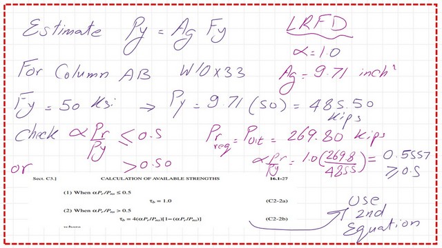
First, check that αPr/Pns < 0.50. Then, we will have τb = 1. If not, τb will be < 1.0.
For the LRFD case, Pr = Pult = 269.80 kips. the yielding load Py=Ag*Fy=9.7150=485.50 kips, αPr/Pns will be=(1269.80/485.50) =0.557 >0.50, then τb<1, but if αPr/Pns<0.50, then τb=1.
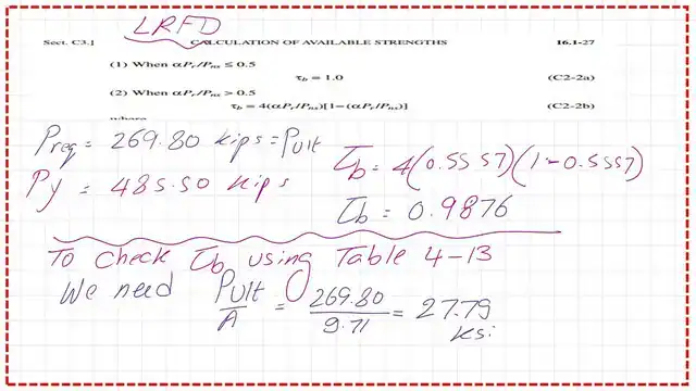
But in our case τb<1, then use this equation τb= 4(αPr/Pns)*(1-(αPr/Pns)).
We substitute the values as τb= 4*(0.5557)(1-(10.5557), τb=0.9876.
We estimate the value of Pult/area=269.8/9.71=27.79 ksi; this is the value we will use to get τb from Table 4-13 .
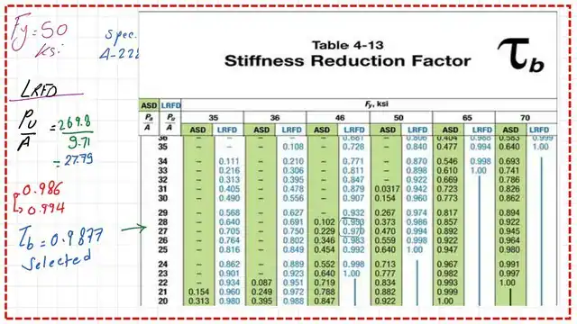
Use Table 4-13 to get τb value -LRFD design.
We have Pu/A=27.79 we move with this value from the horizontal direction and intersect with the column for Fy=50 ksi. The stiffness factor is equal to 0.9877.
We need to adjust the k value, which is done by re-adjustment of GA and GB by multiplying by τb. The adjusted value of Ga=1.52*0.9877=1.5013, while the adjusted value of Gb=1.36*0.9877=1.343 for the solved problem 4-14 part 2 for the effective length factor.
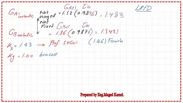
The final Kx value is found to be equal to 1.43 for the inelastic column AB, while Ky=1.0.
ASD design procedure for τb.
For the ASD design, we will estimate kA and KB for column AB The same procedure as we have estimated earlier will be repeated, and check whether the column is elastic or inelastic for Kl/rx>= 4.71*Sqrt(E/Fy).
Based on the estimation, we will find that the column is inelastic, so we need to find τb.
In the ASD calculation, we have D = 35.50 kips and L = 142.0 kips. Pt = 35.50 + 142.0 = 35.50+142.0=177.50 kips
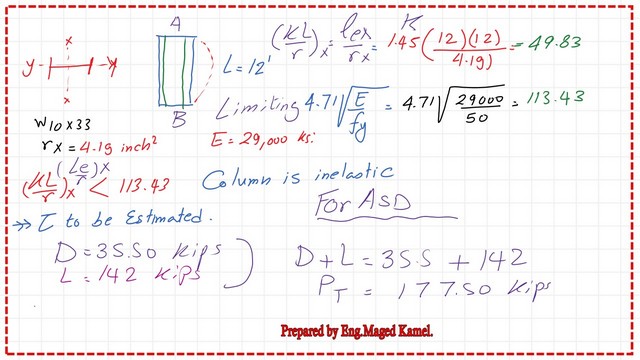
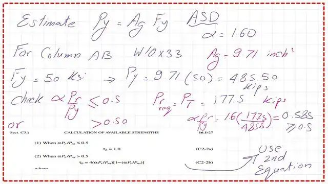
We check if αPr/Pns < 0.50; then τb = 1, α equals 1.60, Pr is Ptotal, which equals 177.50 kips, and Pns is the yield load, which equals A*Fy = 9.71*(50) = 485.50 kips.
Then αPr/Pns=0.585>0.50, τb<1, then use the equation τb= 4(αPr/Pns)*(1-(αPr/Pns)). We calculate a substitute using the known values, and we obtain τb = 0.9703.
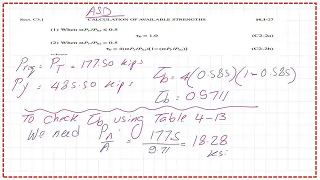
From Prof. Segui’s calculation, τb=0.9703, which is extracted from table 4-13 as shown in the next slide image. How to use the table, 4-13, is shown in full detail for the ASD design.
Use Table 4-13 to get τb -ASD design.
We have Pt/A=177.50/9.70=18.28, we move with this value from the horizontal direction and intersect with the column for Fy=50 ksi. The stiffness factor is equal to 0.9703.
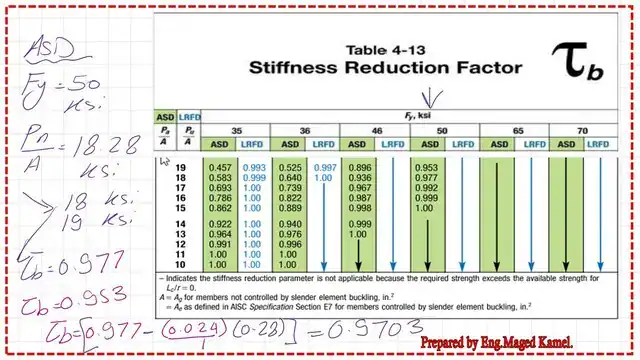
We need to adjust the k value, which is done by re-adjustment of GA, GB, by multiplying by τb.
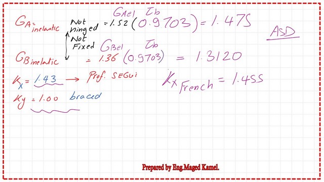
The adjusted value of Ga=1.52*0.9703=1.47, while the adjusted value of GB=1.36*0.9703=1.3432.28 for the Solved problem 4-14 part 2 for the effective length factor.
The final Kx value is found to be equal to 1.43, while Ky = 1.0. I hope this post will add something to the subject of compression steel members.
For the previous post, please refer to Solved problem 4-14-effective length factor-Part 1
A very useful external link. A Beginner’s Guide to the Steel Construction Manual, 15th ed.