Last Updated on November 4, 2025 by Maged kamel
- Solved problem 4-7-Design using Table 3-10 when Lb>Lr.
- Solving problem 4-7 using LRFD design.
- Find the Φb* Mn for W12x35 for Lb=31 Feet and compare with the given Mult.
- Find the Φb* Mn for W16x31 for Lb=31 Feet and compare with the given Mult.
- Find the Φb* Mn for W14x34 for Lb=31 Feet and compare with the given Mult.
- Find the Φb* Mn for W10x45 for Lb=31 Feet and compare with the given Mult.
- Find a new section that has φb*Mrx bigger than the Mult of 170 Ft.kips.
- Introduction to Table 3-10.
- Table 3-10 is used for the LRFD Design.
- Verify the LRFD value at Lb=31.0 FEET.
- Solving problem 4-7 by using the ASD design using Table 3-10.
- Solving problem 4-7 using LRFD design.
Solved problem 4-7-Design using Table 3-10 when Lb>Lr.
We will discuss why we should use Table 3-10 for the design of the section, instead of Table 3-2, for the case where Lb is large, as we will find out.
A solved problem 4-7 from Prof. Alan Williams’s book. A simply supported beam of Grade 50 has an unbraced length of 31′.
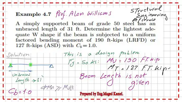
Determine the lightest adequate w-shape if the beam is subjected to a uniform factored bending moment of 190 ft-kips(LRFD) or 127.0 Ft-kips (ASD) with cb=1.0. I have included the steps to be followed; if we start the design by selecting AISC Table 3-2.
Solving problem 4-7 using LRFD design.
If we proceed by using AISC Table 3-2 for the solved problem 4-7, where the W sections are sorted based on Zx. We have Zx estimated preliminarily from the relation (Φb* Mn ) =(Φb* Fy*Zx), then Zx is (Φb* Mn )/Φb* Fy.
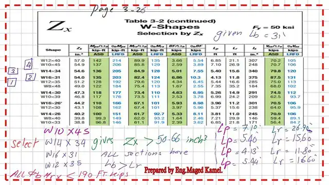
Based on the given data, Fy=50 ksi, Φb=0.90,(Φb* Mn )=190.0 ft. kips, the estimated Zx=50.66 inch4, as we can see from the next slide image.

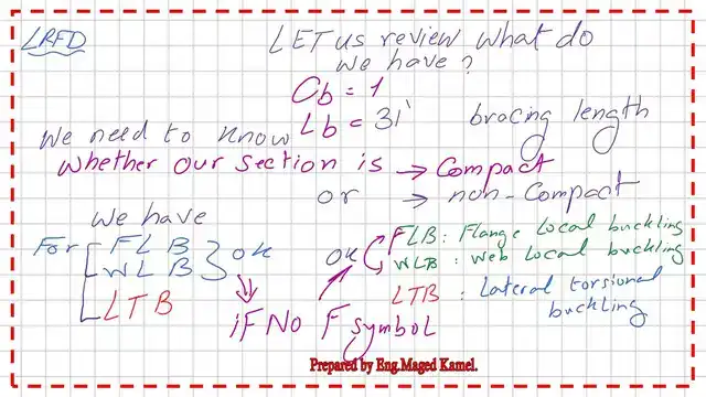
Our section should be checked against FLB, WLB, and LTB. If the section does not have an F designation, it means that no local buckling for the flange or web.
Sorting by Zx, using Table 3-2, we have various sections: W10x45, W14x34, W16x31, and W12x35. All these sections have Zx >50.66 inch4.
We will get the corresponding values of Lp and Lr for each section.
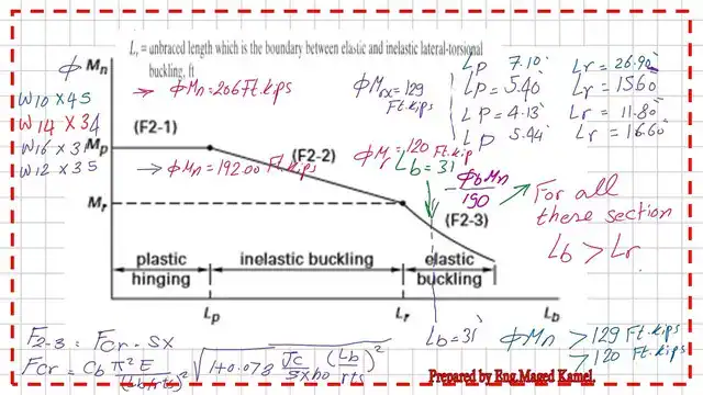
Our Lb is>Lr; for all of the different sections, the factored (Φb* MP) and the factored (Φb* Mr) are sketched for all the chosen sections, yet their capacity (Φb* Mrx) will be from 120.0 ft. kips and 129.00 Ft.kips, while the given Multimate=190.0 ft. kips.
The next slide shows the plot of lb against factored Mn for the four sections of W10x45, W14x34, W16x31, and W12x35. Each beam will be checked after we get its Fcr stress value.
Find the Φb* Mn for W12x35 for Lb=31 Feet and compare with the given Mult.
Our first section is W12x35 with a depth of 12.50 inches. From Table 1-1, we will get all the necessary data to evaluate the Fcr stress since Lb is bigger than Lr.
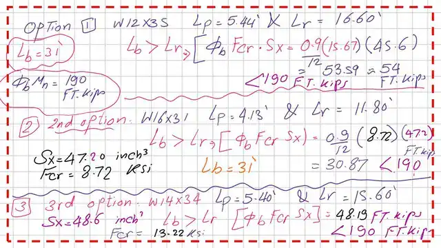
The rts value equals 1.79 inches, C=1, J=0.741 inch4, and ho=12.00 inches. The elastic section modulus Sx equals 45.60 inch3 and Lb=31 feet. We can estimate the elastic stress as equal to 15.67 ksi, since Sx=45.60 inch3. The LRFD Nominal value=0.9*15.67*45.60/12=53.59 FT.kips, which is less than the Given Mult=190 FT.kips.

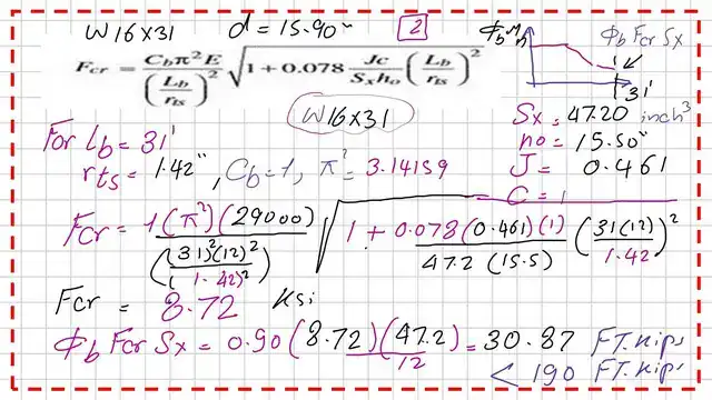
Find the Φb* Mn for W16x31 for Lb=31 Feet and compare with the given Mult.
Our second section is W16x31 with a depth of 15.9 inches. From Table 1-1, we will get all the necessary data to evaluate the Fcr stress since Lb is bigger than Lr.
The rts value equals 1.42 inches, C=1, J=0.461 inch4, and ho=15.50 inches. The elastic section modulus Sx equals 47.200 inch3 and Lb=31 feet. We can estimate the elastic stress as equal to 8.72 ksi, since Sx=47.200 inch3. The LRFD Nominal value=0.9*8.72*47.20/12=30.87 FT.kips, which is less than the Given Mult=190 FT.kips.
Find the Φb* Mn for W14x34 for Lb=31 Feet and compare with the given Mult.
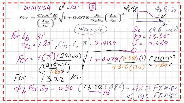
Our third section is W14x34 with a depth of 14.0 inches. From Table 1-1, we will get all the necessary data to evaluate the Fcr stress since Lb is bigger than Lr.
The rts value equals 1.80 inches, C=1, J=0.569 inch4, and ho=13.50 inches. The elastic section modulus Sx equals 48.60 inch3 and Lb=31 feet. We can estimate the elastic stress as equal to 13.22 ksi, since Sx=48.60 inch3. The LRFD Nominal value=0.9*13.22*48.60/12=48.19 FT.kips, which is less than the Given Mult=190 FT.kips.
Find the Φb* Mn for W10x45 for Lb=31 Feet and compare with the given Mult.
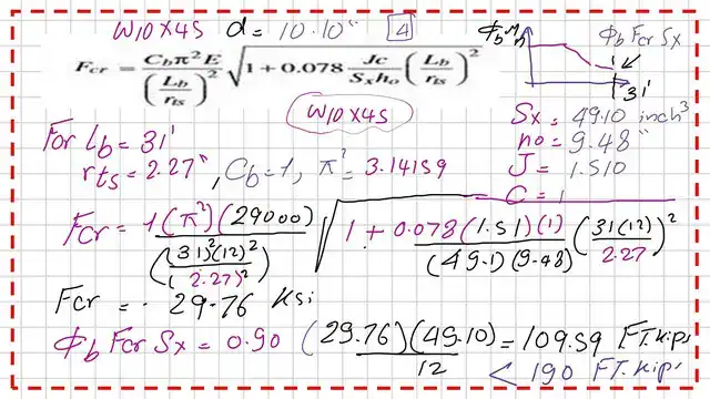
Our fourth section is W10x45 with a depth of 10.10 inches. From Table 1-1, we will get all the necessary data to evaluate the Fcr stress since Lb is bigger than Lr.
The rts value equals 2.27 inches, C=1, J=1.510 inch4, and ho=9.48 inches. The elastic section modulus Sx equals 49.10 inch3 and Lb=31 feet. We can estimate the elastic stress as equal to 29.76 ksi, since Sx=49.10 inch3. The LRFD Nominal value=0.9*29.76*49.10/12=109.59 FT.kips, which is less than the Given Mult=190 FT.kips.
The following slide shows a summary of the LRFD nominal values for the three W sections selected by using Table 3-2.
The following slide shows a summary of the LRFD nominal values for the last W section, W10x45, selected by using Table 3-2.

Find a new section that has φb*Mrx bigger than the Mult of 170 Ft.kips.
This means all these sections cannot carry the given moment since Lb>lr. Again, we have to check other selections for W steel shapes. But this time, we will focus on the sections with Φb* Mrx bigger than 190 Ft.kips.
Continuing to use Table 3-2 will not be our best choice because of the numerous trials we will have to conduct. Since we have 7 sections with Φb* Mrx greater than 190 Ft-Kips.
All the previous four sections fail to give an LRFD nominal strength bigger than the given Fu for a bracing length of 31 Feet. We will select a bigger size with W section, which is W12x58, which has φb*Mrx bigger than 190 Ft.kips. The Zx value is equal to 86.40 inch3>50.67 inch3 as required.

Introduction to Table 3-10.
Instead, we will use Table 3-10. For solved problem 4-7, we have a given factored moment of 190 ft. kips (LRFD) and bracing length Lb=31.’
We will use Table 3-10. The appropriate page is P-3-129 for CM#14 and page P3-122 for CM-15, where lb is from 18′ to 34′ and φb*Mn is between 180 and 240 Ft.kips. The data that we will use is Lb=31 Ft and φb*Mn=170 Ft.kips.
We draw two lines, and the intersection of the two lines is a point ,for which we will select the nearest solid W section.Please refer to the next slide image.
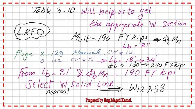
Table 3-10 is used for the LRFD Design.
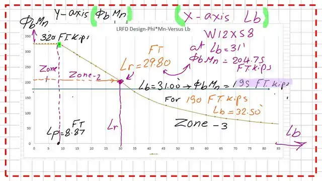
Considering the bracing length Lb=31′, we draw a vertical line. We are interested in the first solid graph, which will give a W-section, which is W12x58. This will be our choice for the corresponding, factored moment φb*Mn=196.0 ft. kips.

This is a graph of the bracing length and the factored moment value for section W12x58. The values of the corresponding factored moment against the different bracing lengths are drawn.
We notice that for Lb=31 feet, the φb*Mn=195.0 Ft.kips>190 Ft.kips. The Lb length that has φb*Mn=190.0 Ft.kips is equal to 32.50 Feet.
We use Table 3-2 to get the Lp and Lr values & φb*Mpx and φb*Mrx and moment slope or gradient for W12x58.
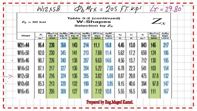
The selected section W12x58 for the solved problem 4-7 has Sx=78.0 inch3 and Zx=86.40 inch3 from Table 1-1. The other related data are also shown in the next slide image.

Verify the LRFD value at Lb=31.0 FEET.
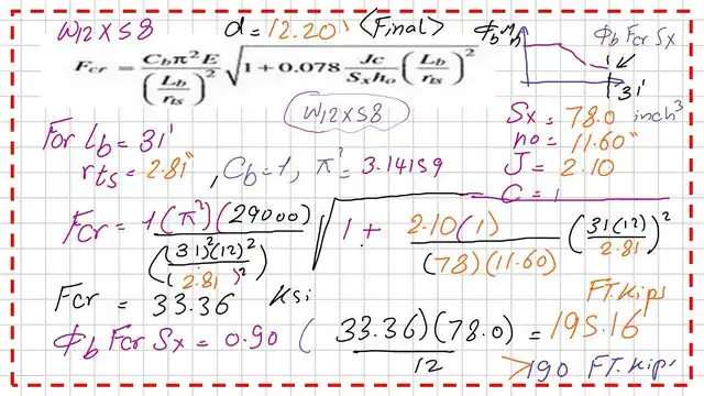
We can verify the value of φb*Mn by using the Fcr value for Lb=31.0 ft, and it is found that Fcr=33.36 ksi, since sx=78.00 inch^3.
The factored(Φb* Mr) value can be estimated as =Φb*Fcr*Sx=0.90*33.36*78.00/12=195.16 Ft.kips; this value is for LRFD.
Solving problem 4-7 by using the ASD design using Table 3-10.
We will use Table 3-10. The appropriate page is P-3-129 for CM#14 and page P3-122 for CM-15, where lb is from 18′ to 34′ and 1//Ωb*Mn is between 120 and 160 Ft.kips. The data that we will use is Lb=31 Ft and Mt=1//Ωb*Mn=127 Ft.kips as given.
We draw two lines, and the intersection of the two lines is a point, for which we will select the nearest solid W section.Please refer to the next slide image.
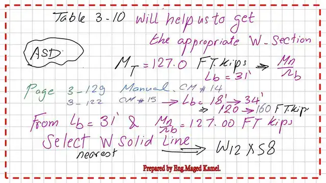
Considering the bracing length Lb=31′, we draw a vertical line. We are interested in the first solid graph, which will give a W-section, which is W12x58. This will be our choice for the corresponding, factored moment (1/Ωb)*Mn=130 ft. kips>127.0 Ft.kips

This is a graph of the bracing length and the factored moment value for section W12x58. The values of the corresponding factored moment against the different bracing lengths are drawn.
We notice that for Lb=31 feet, the Mn/Ωb=130 Ft.kips. The Mpx/Ωb =216.0 Ft.kips

Our estimation for Mn*φb and Mn/Ω will be very close to that obtained by Table 3-10. This is the end of the design process for the W section, as required by solved problems 4-7.
The factored(1/Ωb* Mr) value can be estimated as =(1/Ωb)*Fcr*Sx=(1/1.66)*33.30*78.00/12=129.84 Ft.kips, this value is for ASD.

Please find the PDF file that illustrates the content of Post 16.
Download Download Solved-problem-4.7-select-w-section using Table 3-10 [PDF] For more detailed illustrations of the CB, please follow this Flexural Limit State Behavior.
For the next post, Cb-The coefficient of bending-1/3.