A Solved Problem 4-6-How to Find The Available Flexure Strength?
A solved problem 4-6 for lateral-torsional buckling, when lb>Lp but<Lr.
From Prof. Alan Williams’s book Structure -Reference manual, solved problem 4.6 A simply supported W16x40 beam of grade 50 steel is laterally braced at 6 ft intervals and is subjected to a uniform bending moment with Cb =1.0.
Determine the available flexure strength of the beam.
A solved problem 4-6 from Prof. Alan Williams‘s Structural Engineering Reference Manual. The solved problem is similar to solved problem 4-5, except that, the Lb is increased to 6 ‘.
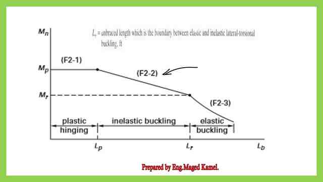
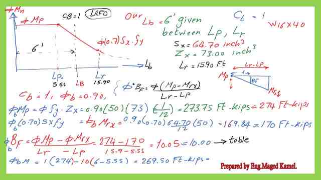
This graph represents the relation between Lb and the nominal moment Mn, it has three zones based on the value of Lb and its relation with Lp &Lr.

Analysis for the given section by the LRFD design.
The solved problem 4-6 is an analysis problem, the section is given for which, the distance between bracing for a beam is Lb > Lp, but Lb <Lr, for the LRFD design.
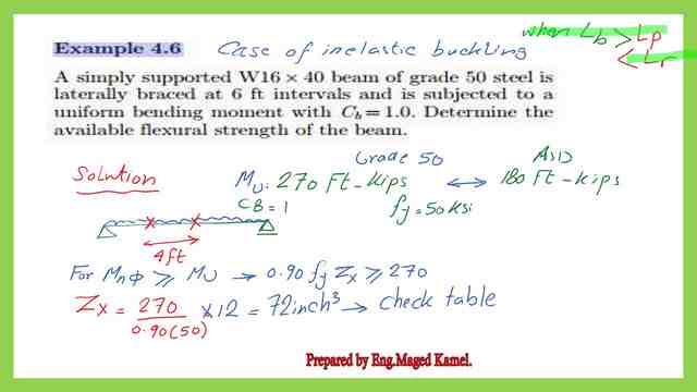


The steps for the solution are as follows:
1-Get the plastic section modulus of Zx value by considering its minimum value by equating the ultimate load by the product of phi by nominal moment. Since the nominal moment equals the product of Zx by Fy, we will substitute Fy by 50 ksi and phi by the value of 0.90.


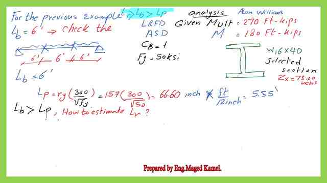
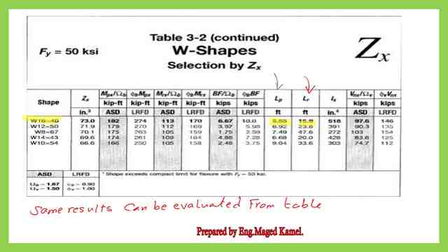
2-Get the maximum un-braced length that will let the shape reach its plastic moment strength Lp. The relevant equation for Lp is introduced from Lp=300*ry/sqrt(Fy). We need to get these data from AISC table 1-1. The Lp value is 5.55 feet. Our given bracing length is 6 feet, the condition is that the bracing length is bigger than Lp. Please refer to the third slide image for more details.

There is another alternative way by using AISC Table 3-2, which we can see from the table that the LP=5.55 FT.
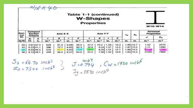

3-Check Lr value either from the following equation or get the value from Table 3-2 for the selected section. The Lr value equals 15.90′.
From the previous equation F2-6, we need the following values from the Torsional properties: J, CW, and other properties, tf, Sx, rts, ho, selected from table 1-1. This is the equation for Lr value for the bracing distance.
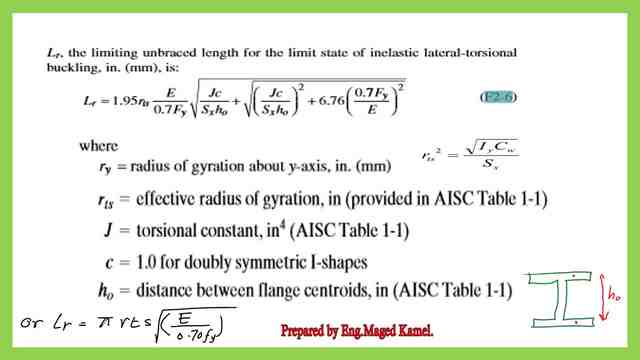

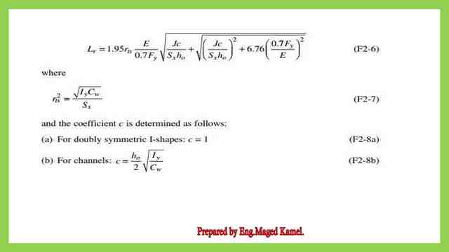
This is the detailed reference equation number as presented in the AISC code.

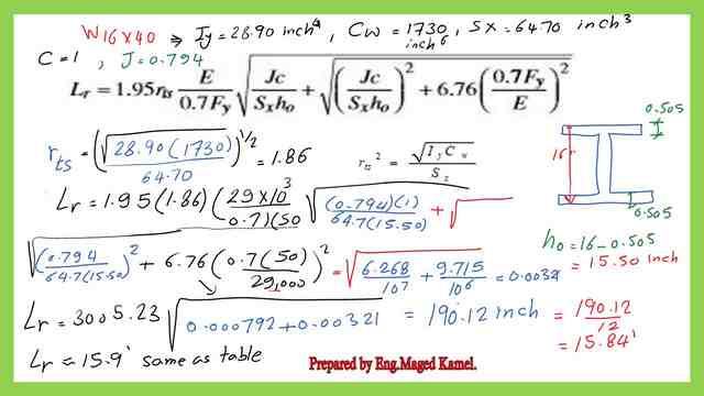
This is the detailed estimation of the value of lr by using the equation.Lr=15.9′.

This is the value of limiting laterally unbraced length Lr by using table- 3-2.

For the given Lb check if Lb>Lp and Lb <Lr, then the section is not compact, the value of φb*Mn is < φb*(Mpx), but φb*Mn > φb*(Mrx), where Mpx=Fy*Zx, while Mrx= (0.70*Fy*Sx).
Estimate φb*Zx*Fy for Lb and φb*Fy*Sx for Lr. Estimate the value of φb *BF.
The final φb*Mn= φb (Zx*Fy)- φb *BF*(Lr-Lb), is explained as per the next picture.
The available flexure strength is based on the LRFD, φb *Mn=269.50 Ft.kips.
This is the value of φbMp and φbMr by using Table 3-2.
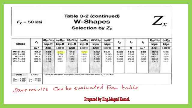

These are the detailed calculations for the LRFD value of moment by using BF as shown in the next slide image.

The analysis for the given section by ASD.
For the ASD design, to get the flexure strength, follow the next steps:
1-Get a preliminary Zx value by considering that φb*Mn=Mult, since Mn=Zx*Fy. We can get Zx from the relation Zx*Fy = Mt / Ω.
2-From table 3-2, select the lightest w section, that gives Zx>Zx preliminary.
3-From table 1-1 we get the Sx value, ry for the selected section, and either estimate Lp. LP= ry*300/ sqrt(Fy), from AISC Table 3-2.
4-Check limiting laterally unbraced length Lr value either from the following equation:
Lr =1.95*rts*(E/0.7 Fy)*SQRT(((J*C/(Sx*ho)+SQRT(J*C/(Sx*ho)^(2)+6.76*(0.7Fy//E)^(2))), or from table 3-2 for the selected section.
If Lr by the equation. We need the following values from Torsional properties: J, CW.
5- For the given Lb check is Lb>Lp and Lb <Lr, then the section is not compact, the value of Mn/Ω is < (Mpx)/ Ωb, > (1/Ωb)*(Mrx)
Mpx=Fy*Zx, Mrx= (0.70*Fy*Sx).
6-Estimate (1/Ωb)*Zx*Fy for Lb and (1/Ωb)* 0.70*Fy*Sx for Lr.
7- The final (1/Ωb)*Mn= (1/Ωb) (Zx*Fy)- (1/Ωb) *Bf *(Lr-Lb).
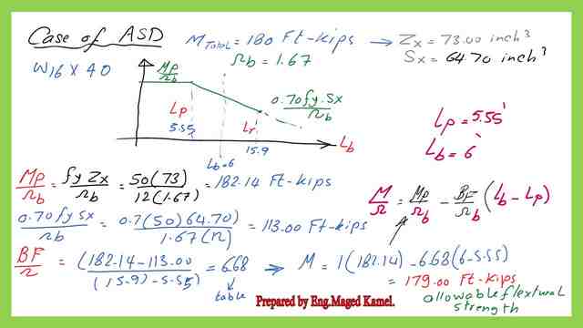
The available flexure strength based on the ASD, (1/Ωb)*Mn=179.00 Ft.kips. This is the value of (1/ Ωb )*Mp and ( 1/Ωb )*Mr by using Table 3-2
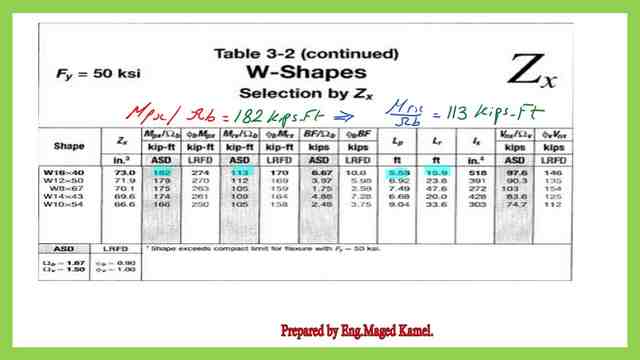

These are the detailed calculations for the ASD value of moment by using BF as shown in the next slide image.

This is a link to download the PDF file used for the illustration of this post.
For a useful external source, please follow the Lateral Torsional Buckling Limit State
This is the solved problem 4-5.
For the next post, Solved problem 9-7, When Lb>Lr, what is flexure strength?

