Last Updated on October 17, 2025 by Maged kamel
- Solved problem 4-5- Design a steel beam-(lb less than lp).
- A solved problem 4-5-Problem statement.
- Design of the beam according to LRFD for part a.
- Design of the beam according to ASD for part a.
- Check your understanding by solving the following Quiz.
- Design of the beam according to LRFD for part b.
- Design of the beam according to ASD for part b.
- Download the full PDF solution
Solved problem 4-5- Design a steel beam-(lb less than lp).
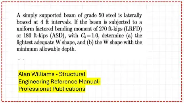
A solved problem 4-5-Problem statement.
A solved problem 4-5 is quoted from Prof. Alan Williams‘s Structural Engineering Reference Manual, 8th edition, based on various given Ultimate /working moments and a given bracing length. As a first requirement, the lightest W section must be determined, and a W shape with minimum allowable depth must be selected as a second option.
Design of the beam according to LRFD for part a.
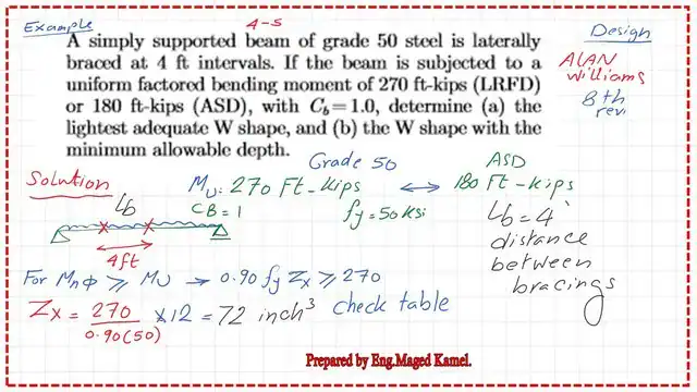
Part A includes the choice of the lightest adequate W section for design. We must identify which region the section is located in according to bracing. This is a design problem for which the distance between bracing for a beam is Lb < Lp.
For the LRFD design:
1-Estimate the preliminary Zx value by considering that φbMn=Mult, since Mn=Zx*Fy, we can find the value of zx, which will be equal to 72 inch3.
The next slide shows a sketch of how Tables 1-1 and 3-2 can be used to select the required section and find the design strength.
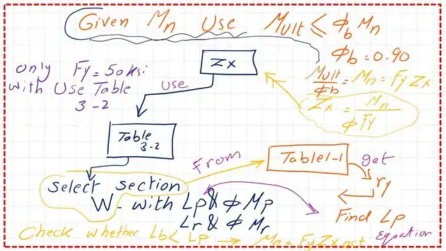
We can get the plastic section modulus Zx= Mult /(φb*Fy). We go to Table 3-2, where sections are sorted by Zx, and select the first bold section with Zx selected > Zx estimated.
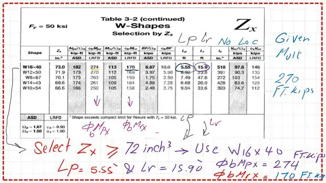
2- From Table 3-2, we get the first bold section, W16x 40, which has Zx =73.0 inch3 >72.0 inch3 value required by the preliminary value for Zx.
The bracing length required can be obtained from Table 3-2 at the plastic stage Lp and Lr values. The Lp value is 5.55 FT, while Lr is 15.90 ft. We have given the bracing length as 4 ft, which indicates that we are in zone 1.
The steel section W16x40 has no f symbol, meaning there is no problem with local buckling.
This is a reminder about the Mn graph, the bracing distance, and the different zones—the value of Lp according to Fy and the radius of gyration ry. The x-axis represents the bracing length, and the y-axis represents the Nominal moments.
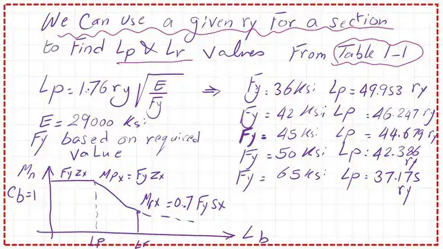
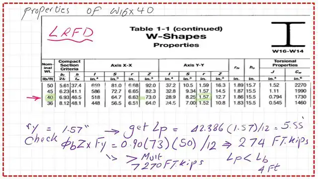
3- From Table 1-1, we can check the Lp value and find the φb*Mn.
This is part 2 of Table 1-1 for W actions with Fy=50 ksi. Based on the beam weight of 40 lb/linear ft, the radius of gyration is about y =1.57 inches.
The section is compact since the given bracing length Lb is smaller than Lp. The value of φb*Mn= φb*Zx*Fy is to be divided by 12 to get the value in Ft-kips-LRFD. 4-We get the φb*Mn=274 ft. kips.
The exact value φb*Mn can be obtained from Table 3-2, as seen in the next slide.
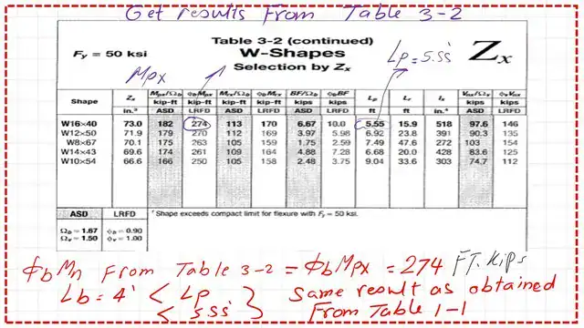
We can see that φb*Mn is bigger than the given ultimate moment of 270 ft-kips.
Design of the beam according to ASD for part a.
The ASD calculation is shown in the next slide; here are the following steps to implement:
1-Get a preliminary Zx value by considering that (1//Ω)*Mn=Mtotal, since Mn=Zx*Fy.
We can get Zx= Mtotal /(1/Ω)*Fy). 2- From Table 3-2, select the lightest w section that gives Zx>Zx preliminary.
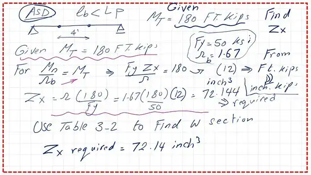
The selected W section is W16x40, and its Zx is 73.00 inch3, which is >72.144 inch3, as required.
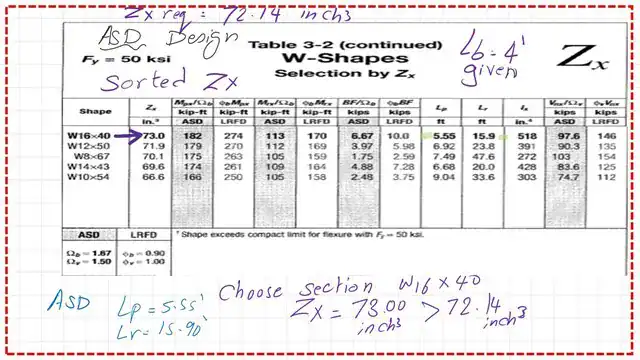
2—From Table 3-2, we get the section W16x 40 with Zx =73.0 inch3 >72.0 inch3, the preliminary value for Zx.
The bracing length required can be obtained from Table 3-2 at the plastic stage Lp. Lp can be estimated from the relevant formula Lp=ry* (300/sqrt(Fy)), but we need the ry value.
3- From Table 1-1, get the Sx value, ry, for the selected section. Find the value of lp.
4- Since the given bracing length Lb is smaller than Lp, the section is compact, (1/ Ω)*Mn = (1/ Ω)*Zx*Fy, to be divided by 12 to get the value in Ft-kips-ASD.
5- Check that the estimate (1/ Ω)*Mn is > the total moment Mt.
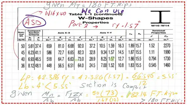
The exact value (1/ Ω)*Mn can be obtained from Table 3-2, as seen in the next slide.
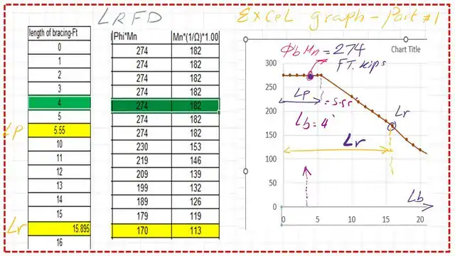
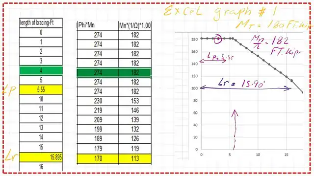
I have added two graphs from an Excel sheet to show the values of φb*Mn and the value of (1/ Ω)*Mn for a bracing length of 4 feet; the section is W16x40 part a.
Check your understanding by solving the following Quiz.
Two quizzes are introduced to check your understanding. Please sign in to get a verification of your answer via email.
Results
The lp value equals=1.76ry*sqrt(E/Fy). For fy=36 ksi, lp=49.953*ry.since ry=1.57″, lp=49.953*1.57=78.43 inches=6.54 feet.
HD Quiz powered by harmonic design
#1. What is the plastic bracing length lp for W16x40 steel beam of steel grade 36?
The lp value equals=1.76ry*sqrt(E/Fy). For Fy=36 ksi, lp=49.953*ry.since ry=1.57″, lp=49.953*1.57=78.43 inches=6.54 feet.
#2. What is the plastic Moment for W10x60 of grade 36? Select the closest answer from the following choices.
The plastic moment = FyZx = 36*74.60 = 2685.6 inch-kips; dividing by 12, we get 223.8 approximately=224 ft. kips.
Design of the beam according to LRFD for part b.
Why do we select W10x60?
Part B determines the W shape with minimum allowable depth, as per LRFD.
The selection is based on the minimum depth. We will select W10x60 since the depth is smaller < depth of W16x40, as shown in the next slide, then check that the φb*Mn> Mult.
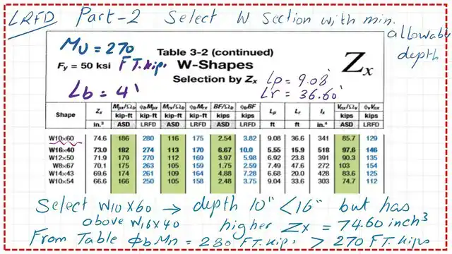
The φb*Mn of the selected section is bigger than 270 ft. kips.
Design of the beam according to ASD for part b.
This is part b, W shape with minimum allowable depth, as per ASD, for the selection based on the minimum depth.
We will select W10x60; since the depth is smaller than the depth of W16x40, as shown in the next slide, then check that (1/ Ω)*Mn > Mt.
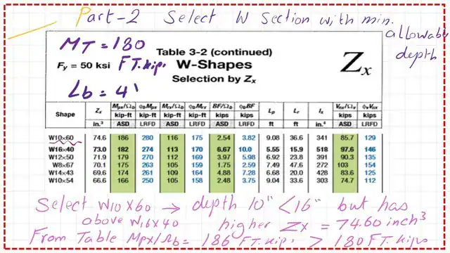
I have added two graphs from an Excel sheet to illustrate the values of φb*Mn and (1/Ω)*Mn for a bracing length of 4 feet; the section used is W10x60 for part b. Thanks a lot.
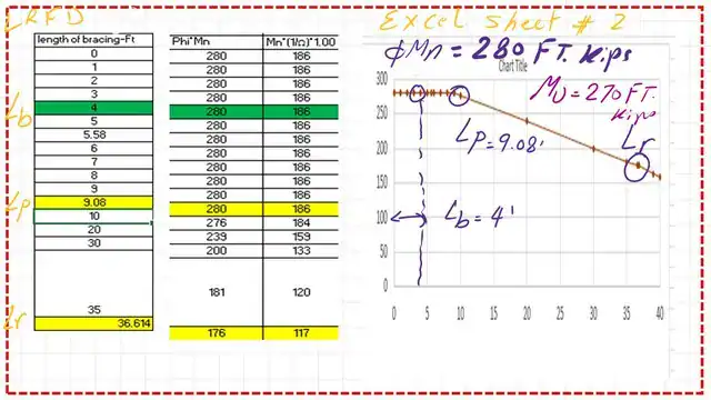
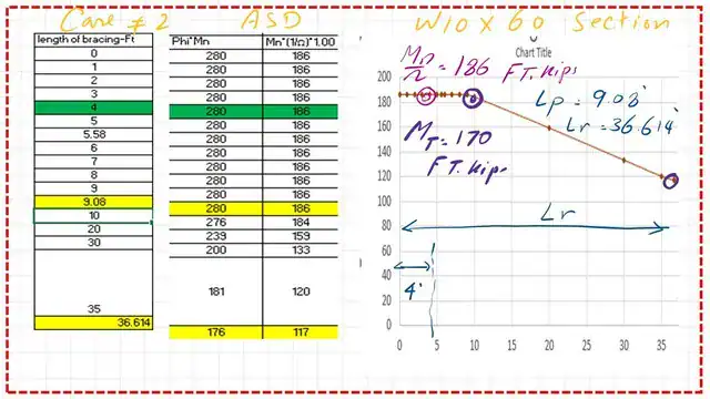
Download the full PDF solution
The PDF file that includes the data of this post can be reviewed and downloaded.
This worked solution follows AISC provisions to design a steel beam where the unbraced length lb is less than lp.
Download solved problem 4‑5: design a steel beam (lb < lp) [PDF]For a valuable external source, please follow this link: Lateral Torsional Buckling Limit State.
Review the information for Lp and Lr for the next post. This post introduces the different terms for Lp and Lr for a steel beam.