Last Updated on August 31, 2024 by Maged kamel
- local buckling parameters for steel beams.
- The relation between Nominal Moment Mn, the λ Values, and the three regions.
- The slenderness ratio values for the non-compact sections.
- What are the unstiffened -elements?
- How do you estimate the bf for the un-stiffened elements?
- What are the stiffened elements?
- How do you estimate h for stiffened elements?
local buckling parameters for steel beams.
The relation between Nominal Moment Mn, the λ Values, and the three regions.
The topics included in our discussion are shown in the next slide.
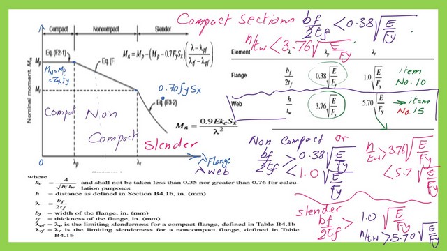
The relation between λ and Mn can be viewed in three regions. The first region is the compact region, which we call F2-1, chapter F provision 2 equation 1-which states that Mn=Mp=Zx*Fy.
To determine the plastic modulus Zx, we must evaluate the lambda and its value to reach this first region.
To get a compact doubly symmetric W section, for instance, bf/2tf<λpF or 0.38*sqrt(E/Fy) and h/tw<λpw or less than 3.76*sqrt(E/Fy).
To get a non-compact W section, bf/2tf >λpF or 0.38*sqrt(E/Fy) and smaller than λrF or 1.0*sqrt(E/Fy) and h/tw>λpw or 3.76*sqrt(E/FY) and less than 5.70*sqrt(E/Fy).
To get a slender W section, bf/2tf >λpr or 1.0*sqrt(E/Fy) and h/tw>λrw or 5.70*sqrt(E/Fy).
Please refer to the next slide image for more details.

We must evaluate the lambda and its value to determine Zx to reach this first region. The lambda value λ should be from 0 to λp for the first zone.
For the second region represented by the equation, the Lateral-Torsional buckling region, F2-2, the value of the line for the second region starts from Mn=Mp and ends at Mn=0.70 Fy*Sx.

The value of 0.70 Fy at the other end is due to the residual stresses during fabrication. The residual stress will cause Internal stresses in opposite directions. So 0.30 Fy*Sx is reduced from the Mn.
We have a linear equation for the second region.
If your lambda value λ is between λp and λr, then the line equation Y=mx will be Mn=Mp- (the difference between the x’s)(λ-λp).
The final form will be Mn=Mp-(Mp-0.70FySx)*((λf-λpf) /(λrf-λpf), where λrf for limiting slenderness for Flange as an upper limit on non-compact.
What are the values for λp?
For the Flange, our lambda is λF= (Bf/2Tf) used to estimate λF.
While in the case of the web, λw= (h/tw), is used for the estimation of λw.
The first local buckling parameter for the flange is λpf, which is = 0.38*sqrt (Et/Fy).
For instance, if Fy=36 ksi, put the value of 36 inside the sqrt. λpf =0.38*sqrt(29000/36)=10.785.
The first local parameter λpf for Fy=50 ksi,λpf=0.38*sqrt(29000/50)=9.15.
For the web, the first local parameter λpW for web =3.76*sqrt(E/Fy). Again, the numerator will be set =3.76*sqrt(29000/36)=106.717 for Fy=36 ksi.
We can use the sketch of the three regions in the two cases of Flange and Web, but consider the different value λp for each case for Flange and Web.
The slenderness ratio values for the non-compact sections.
The non-compact section slenderness ratio starts from λp till λr.
λr will be our second local parameter.
For the value of λr for flange λrf, for A 992 steel with Fy=50 ksi, for the case of flange λrf=1.0*sqrt(E/Fy)=1*sqrt(29000/50)=24.08.

While the second local parameter. for Fy=50 ksi, λr equation for the web equals 5.70*sqrt(E/Fy)=5.7*sqrt(29000/50)=137.27.
What are the unstiffened -elements?
Unstiffened – elements are elements that are supported only at one edge, for example, the flange of the W section and the flange of C -the channel.
How do you estimate the bf for the un-stiffened elements?
The code defined the value of b, which is used in estimating slenderness for four items. The first item is for an I-shaped member, where b is 1/2 the full flange width of bf.
For the second case, where the section for legs of angles and flanges of channels and zees, b, is the full leg width, refer to item 12, Table B4.10.
For the third case, where the section is a plate, b is the distance from the free edge to the first row of fasteners.
For the fourth case w, here the section is the stem of tees, d is the full depth of thction item no.14.
If we check Table B4.1b, which gives the ratio between width to thickness for members subject to flexure, item 10 is for flanges or rolled I beams, and item 11 is for flanges of doubly or singly Symmetric I-shaped built-up section.
The list from No.10 to No. 14 for the un-stiffened elements and the λp, the first local buckling parameter for members subject to flexure. The limiting slenderness of the compact flange. The second local buckling parameter, λr, limits the non-compact flange’s slenderness.
What are the stiffened elements?
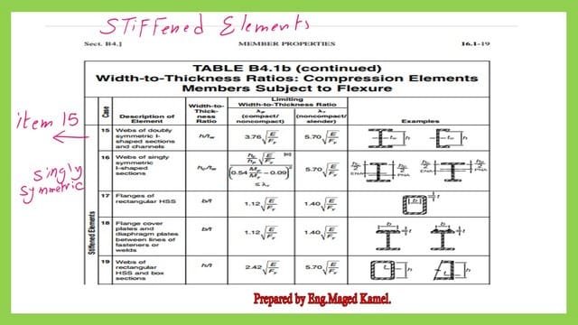
Stiffened elements are those supported at two edges, such as the web of the W section, the web of the C channel, and the tube sections.
How do you estimate h for stiffened elements?
The B4.1 Table shows the different elements and how to find the h value.
There is also a graphical table for the unstiffened elements, so check items from 10 to 14. Items 1 to 9 are for the elements subjected to axial compression.

The list from No.15 to No. 20 for the stiffened elements in Aisc-360-10.
The stiffened item list in AISC-360-10 has only 20 items; please refer to the next slide image.

These tables show the values of λp, the limiting slenderness for a compact flange, and λr, the limiting slenderness for a non-compact flange. The AISC360-16 has 21 items, the last three of which are shown in the next slide image.
For the buckling concept, please refer to this link from Prof T. Bart Quimby, P.E., Ph.D., F.ASCE site.
This is a link for the next post, 8- How to make an analysis of steel beams? Solved problems.