Last Updated on October 5, 2026 by Maged kamel
Mohr’s Circle of Inertia part 2.
Point of minimum Value of Inertia.
We will continue our discussion about Mohr’s circle of Inertia in part 2. Part 1 illustrated how to draw Mohr’s circle of Inertia and find the values of Imax, Imin, and Ixy. The next question is: how can we see the principal axis directions?
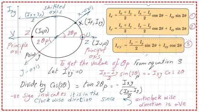
The Point of the minimum Value of Inertia is Point Z’, where the Ixy Value equals zero. What about the direction of the V axis?
The direction is obtained from Mohr’s circle of Inertia by an angle of (180-2θp) anticlockwise from the Y-axis, or (2θp) clockwise from the Y-axis.
In the Normal view, it has an angle of (90- θp) from the x-axis in the anticlockwise direction.

The Expression of tan 2θp.
In Mohr’s Circle of Inertia part-2, estimate 2θp from the third equation by setting Ixy to zero. This will give the tan (2θp) Value equal to (-Ixy/(Ix-Iy/2)). The negative sign indicates a clockwise angle.
Express Imax using Mohr’s circle.
The Value of Imax, or Iu, can be estimated as the distance from Ixy to the center of the circle, which equals (Ix + Iy)/2 plus the radius. By checking the tan 2θp Expression, we can draw an angle and obtain the radius values for Ixy, Ix, and Iy.
Please refer to the next slide for the derivation of the radius R.

The Expression of Imin using Mohr’s circle.
From the next slide in Mohr’s Circle of Inertia part-2, Imin (or Iv) can be estimated as the shift, which is (Ix+Iy)/2 minus the radius.
From the tan 2θp Expression, we can draw an angle, find the radius of Ixy, Ix, and Iy, and subtract (Ix+Iy)/2.

The Expression of the pole Point.
The pole Point in Mohr’s circle of Inertia is the Point from which you can get the direction, and the circle’s center is the pole Point when you are dealing with central angles not in the normal view. When you join Point X, it gives the X-axis.
When you join Point Y, you get the Y direction. Similarly, a line from the circle’s center to Point Z gives the principal maximum, or U, direction.

The pole Point in Mohr’s circle for the normal view.
From the last slide, we can get the pole of the standard view as Point Z ‘, joining the mirror Point of x, which will give the U direction in the normal view, and joining the mirror of Point y will give the V direction.
The U direction makes an angle θp from the x-axis, measured clockwise. For the V direction, it makes an angle of (90-θp) from the same axis, but in an anticlockwise direction. This maintains a 90-degree angle between the U and V axes, which is opposite the 180-degree view from the center of the circle.

Thanks a lot, and peace be upon you all.
You can view or download the PDF data for this Post and the previous one. In the previous posts, the slides cover subjects 1-7. For this Post, the slides start at number 8 and continue to the end.
A video covers the topic of the previous Post and this Post.
The following Post is an easy approach to Mohr’s Circle of Inertia-First Case.
This Link is to a useful external resource: a calculator for Cross-Section, Mass, Axial and polar Area Moment of Inertia, and Section Modulus.