Last Updated on September 9, 2026 by Maged kamel
Workable gauge lines for distances at an angle.
The Workable gauge Line distance for an angle is essential for finding the net Area for staggered Bolts in tension.
Types of limit states for Tension Members.
This summarises the Limit states for tension members; two conditions are considered: Yielding and rupture.
We will review the essential equations for the nominal strength of tensile members based on failure mechanisms. If Yielding, Pn = fy*Ag, where Fy is the yield stress, and Ag is the gross Area.
The parameter of the LRFD is φt=0.90, while the parameter of the ASD is Ωt=1.67.
A fracture occurs, splitting the material and passing through line-crossing bolts.
For the second case of tensile rupture, the LRFD parameter φt=0.75, while Ωt=1.67=2.0.
Our main equation, Pn = fult*Aeff, compares the two cases and selects the lesser value after considering the application of the various coefficients. When comparing LRFD cases, include φt in the check.
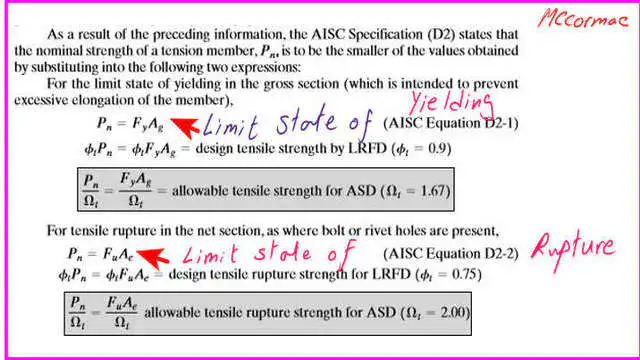
For ASD, consider Ωt for each failure case, then take the minimum across cases. The following slide shows Table 2-4, which lists various shape types.
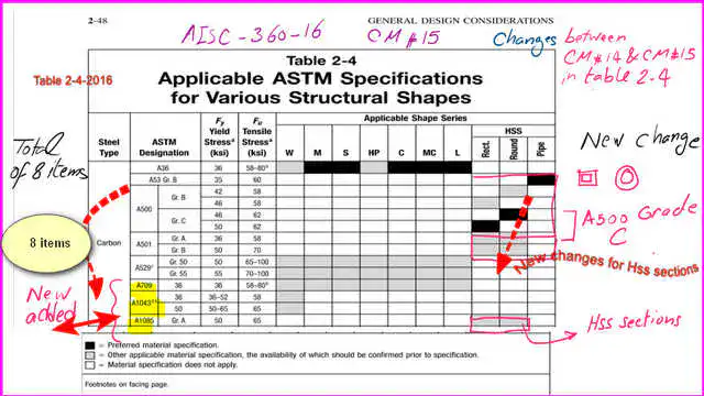
Table 2-5 contains the Applicable ASTM specifications for plates and bars. Table 2-5 contains the Applicable ASTM specifications for Plates and bars.

Detailed Sketch for the gauge lines.
The following slide reviews the gauge lines. The first gauge line and the second gauge line are in the direction of the force, and the difference between g and s is the distance between bolts.
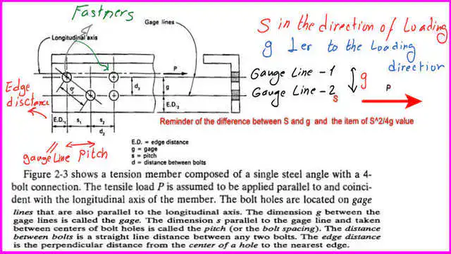
The vertical distance between the gauge lines is g, and the distance between the centerlines of bolts is S, which is called the pitch.
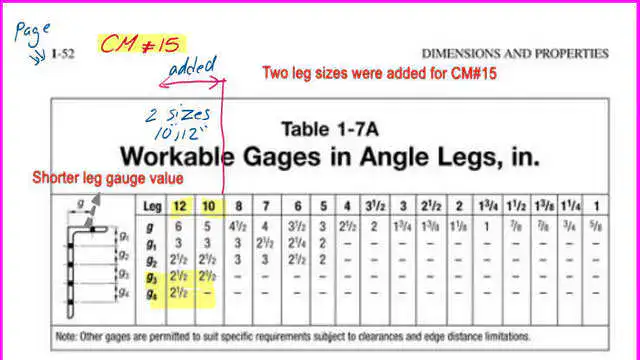
Workable gauges in angle legs in inches- Table 1-7A-CM#15.
The following slide includes Table 1-7A for equal or unequal angles based on CM#15.
This table gives the workable gauges for angle legs in inches. For instance, in our example of 6×4-inch angles, if we want to place one line of bolts along the leg, use the first horizontal, represented by g, for the 6-inch leg. We select 3 1/2 inches for one leg and 4 inches for the other. We are only allowed one gauge line, 2 1/2 inches from the edge.
For a leg with an angle of 6 inches, we can use two gauge lines, g1 and g2. The distance for g1 is 2 1/4 inches, while the second gauge line is 2 1/2 inches.
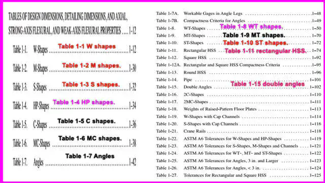
Tables for various structural shapes.
The tables show the different shapes. We can get the required properties, such as Area, Ix, Iy, rx, and ry.
HP shapes, C shapes, and C and MC shapes: angles to get the required properties, Area, Ix, Iy, rx, and ry, etc. W shapes, wide Flange shapes, and M shapes.
Starting from -30 in the AISC manual, pages 30 to 31, data for the S shape from page 32, then HP shapes for pile sections, C channels from 1-36, while for the MC shapes from 1-38, and the angles from page 1-42.
Table 1-1 for W shapes.
Table 1-2 for M shapes.
Table 1-3 for S shapes.
Table 1-4 for HP shapes.
Table 1-5 for C shapes.
Table 1-6 for MC shapes.
Table 1-7 for angles. Other shapes are shown on the next slide.
The vertical distance g between Bolts for an angle.
The following slide shows how to estimate the gauge distance for an angle by using the centerline distance between the bolt centers.
From Prof. Salmon’s book, if there is a section on an angle. The given ga is the first gauge line, as shown on the lower side of an angle, measured from the angle’s edge to the fastener’s centerline. At the same Time, gb is the distance measured vertically from the edge to the fastener’s centerline.
g stands for the gauge distance between the bolt centerlines, estimated by converting the angle into a plate viewed from the inner side of the angle.
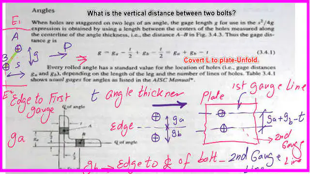
The distance between the centers of the bolts is g = ga + gb – t/2-t/2, so finally=ga+gb-t, where t is the thickness of the angle.
The following post covers problems on net Area estimation.
You can view and download the PDF file for this post from the following link.
For a good reference, here are the types of tension members in structural steel construction.
For a more detailed illustration of block shear, here is a useful external link to a failure-path example: A Beginner’s Guide to the Steel Construction Manual, 14th ed.
A useful external link: Tensile Yielding and Tensile Rupture. A Beginner’s Guide to the Steel Construction Manual, 15th ed.
A useful external link: Tensile Y: Tensile Yielding and Tensile Rupture. A Beginner’s Guide to the Steel Construction Manual, 16th ed.