Last Updated on April 1, 2026 by Maged kamel
- Part 3/4 for the Solved Problem 9-9-6, How To Find LL?
- The limiting coefficient Lp/ry for the built-up section.
- Check lateral-torsional buckling: the Lp value for the built-up section.
- Part 3/4 Of The Solved Problem 9-9-6, the equation of Lr.
- Review of J polar for non-round shapes.
- Review of J polar for the non-round shapes.
- J- value for the built-up section.
- Estimation of the coefficient of bending, cb.
Part 3/4 for the Solved Problem 9-9-6, How To Find LL?
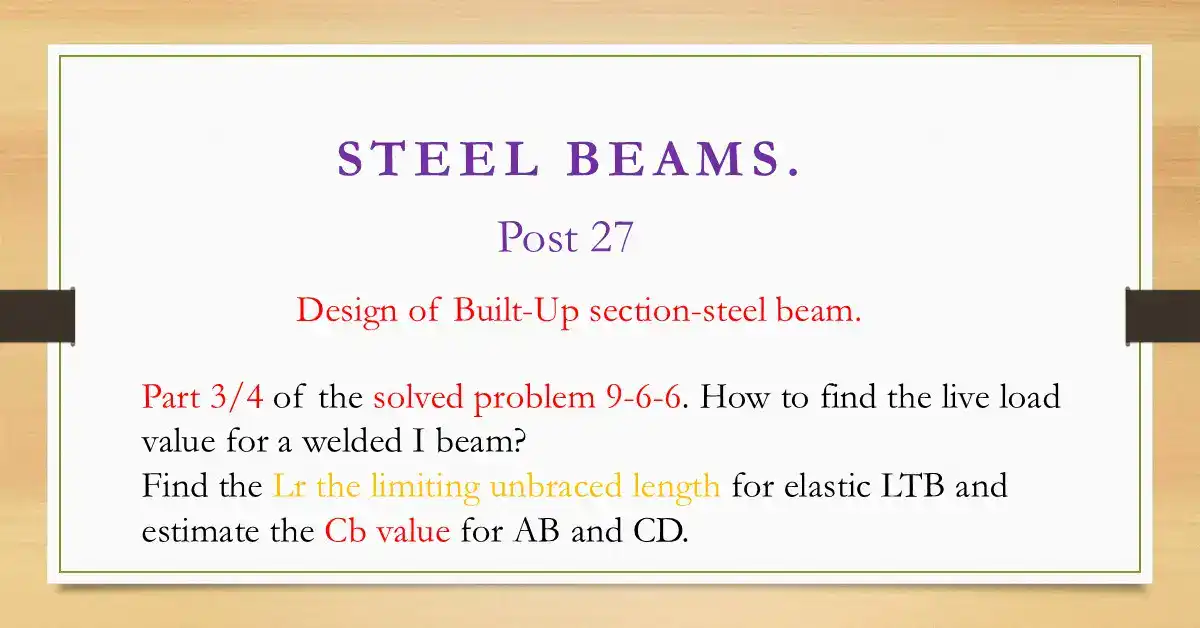
The following slide image illustrates the content of post 27.

The limiting coefficient Lp/ry for the built-up section.
As we can see from the beginning of our solved problem, that the bracing distance=15′, we want to get the Nominal moment due to lateral-torsional buckling and compare the value obtained against Mn due to Local buckling.
How to get the ry? It is obtained from the relation r^2y = Iy/A; then we estimate Lp/ry, where Lp/ry = 300/sqrt(Fy).
In our part 3/4 for the solved problem, where Fy=65 ksi, Lp/ry limiting ratio =300/sqrt(65)=37.21, then the value is to be multiplied by ry.
After estimating its value, we have a rather tough equation for Lr. First, we will estimate the ry value for our built-up section, where r^2y = Iy/A. We have a two-flange and one web; then, Iy can be estimated by the relation Iy = parallel*perpendicular^3/12, where flange = (5/8)*(16^3/12).
Multiply by 2 to include the lower flange. While for the web, Iy web = (26)*(5/16)^3/12. Then Iy for the section=426.74 inch4.
Check lateral-torsional buckling: the Lp value for the built-up section.
The total area At, we have estimated earlier as At/2=14.0625 inch2. Then At=2*14.0625= At=28.125 inch2.
ry = sqrt(Iy/At) = sqrt(426.74/28.125) = 3.895 inch; that is the value of ry. The radius of gyration for the Y-axis, then the plastic distance between bracings Lp, limiting value=37.21*3.895=145.00 inch.

To convert to ft, divide /12=145/12=12.077 feet, Lp=12.10′. In our solved problem, part 3/4, the span is 45 feet, and the distance between bracings Lb=(L/3)=15″. L bracing=15′, the author aims to discuss the section in the second zone where Lb>Lp and <Lr.

Part 3/4 Of The Solved Problem 9-9-6, the equation of Lr.
Let us estimate each item: Cw = Iy*h^2/4c^2, Iy = 426.74 in^4. The Mn value is between Mnp=1728 ft-kips and Mr=1114 ft-kips, but for Lr relation, Lr=1.95*rts* (E/0.70Fy)*sqrt(J*c/Sx*ho*sqrt(1+sqrt(1+6.76Fy*(0.7*Fy*Sx*h0/(E*j*c)^2.
Let us estimate each item Cw= Iy*h^2/4c^2, Iy=426.74 inch4, ok, to estimate then ho=(27.25-5/8)=26.625 inch.
ho^2=(26.625)^2 inch2, taken as ho^2, to review the relation, ho is the distance between the CG of flanges.
The overall distance=total height-(tf/2)),Cw=426.74*(26.625)^2/ 4* c^2, where c=1 for doubly symmetrical sections.cw=75628 inch6.For r^2ts =sqrt(Iy*Cw/ry).
The equation rts = (sqrt(Iy*Cw)/Sx), where Iy = 426.74 in^4 and Cw = 75628, I have estimated all these values because we cannot use the AISC tables for built-up sections.
r^2ts= sqrt(426.74*7.5628)/Sx, where Sx=294 inch3. then r^2ts=sqrt(426.74*7.5628)/294=19.32, then rts=4.395 inch
We will estimate Lr=1.95*rts*(E/0.70*Fy), ts=4.395, E=29000ksi, Sx=294 inch3, Fy=65 ksi. This bracket value(1.95*4.395*29000/0.70*65)*sqrt(J*C)/sqrt(Sx*ho) where J is the torsional constant first, C=1, Sx =294, ho=26.625″.
The big square root, but first I have estimated the value of (1.954.39529000/0.7065)1/sqrt(29426.625) as 61.7395, then multiplied by sqrt(J1)sqrt(1+sqrt(1+6.67(0.765)(29426.625^2/(29000J*1).

I have computed most of the items for the square roots, except for the J value, which we estimate. The square roots are rewritten as sqrt(1+sqrt(1+6.76*12.815/ j^2).

Review of J polar for non-round shapes.
From Prof. Beer’s handbook, chapter 3: If we have a fixed circular at one end, the longitudinal axis will be wrapped due to the torsion, and point A will move up to become point A’.
The torsion causes an angle φ, and the torsion=R*φ causes the rounded portion movement.
The shear strain γ is the change of the length /original length = radial angle = tan γ = γ=R*φ/L.
As we recall, the bending moment stress, f = M*Y/I, causes compression at the top and tension at the bottom. However, that equation is for the bending moment.

Now that we have a torsion, τ, the shear stress, τ max, will be used instead of the bending stress, f.
The torsion moment T will replace M, while R will replace y-max in the case of bending moment, since the section is round, where R is the radius. Instead of I, the polar moment of inertia I-polar will be used.
If polar is considered Jp, then the equation will be τmax = T*R/Jp; the strain γ = R*φ/L, but as strain = τmax/G.
G instead of I to be used, but τmax=T*R/J. γmax= R*φ/L=T*R/Jp. Finally, we obtain the expression φ = T*L/(Jp*G).
Review of J polar for the non-round shapes.
For the non-round shapes, there is torsional fixation on one side.
If we look at an element of length L, due to opposite Torsional moments, one at the fixed part, the other at the free end, both act against each other.
Check the τmax and φ in this case. Using the mathematical theory of elasticity for a straight bar with a uniform rectangular cross-section, then τmax =T/c1*ab^2, where a is the longer side length. At the same time, b is the shorter distance.
While φ=TL/Jpg will be replaced by TL/(c2ab^3)Jp as if Jp=c2ab^3, where c1 and c2 depend on a/b. The c1=c2=1/3(1-0.63b/a) for case of a/b>=5 only.
J- value for the built-up section.
The built-up section, where the web height is greater than its width, can be considered a group of rectangles.
For c1 =c2 to be used at infinity, c1=c2=1/3 and Jp =1/3*a*b^3. Now refer to the next slide, where J =1/3ab^3, then φ= TL/((1/3)ab^3G) for the case of a rectangle. J will be the sum of 1/3ab^3 for the I beam, where a is the longer side, while b is the shorter side.
Now refer back to Lr for the value of J, which is the sum of(1/3)*a*b^3 or 1/3*sum of (longer side)*(shorter side)^3.
For the flange at top and bottom, a=16″, b=5/8″, for the web a=26″ and b=5/16″, J=1/3(16*5/8^3*2+ 26*(5/16)^3). J=2.868 inch3.


For the Lr=61.7392*sqrt(2.868)*sqrt(1+sqrt(1+123.25/(2.868)^2.
This is a detailed calculation to find the final value: Lr=104.575* (3.4897) divided by 12, Lr=30.41. Lb is>Lp and <Lr.
Estimation of the coefficient of bending, cb.
The next step is to estimate the bending coefficient, Cb, to continue calculating Mn for lateral-torsional buckling. I have started with parts AB and CD, which are similar. Estimate the moment values for four portions. Please refer to the first part of the next slide.

The following slide shows the moment values for the 2nd- and 3rd-quarter points.


The following slide shows the detailed calculation for the Cb value for Part AB.

These are the CB values for parts AB and CD. The value is close to 1.46.

The next post will include the required Final Live Load value.
The PDF used for this post can be viewed or downloaded from the following document.
This is the next post, Part 4/4, on Solved Problem 9-9-6. How To Find LL?
Here is the link to Chapter 8 – Bending Members, section, A Beginner’s Guide to the Steel Construction Manual, 14th ed.
Here is the link to Chapter 8 – Bending Members, in A Beginner’s Guide to the Steel Construction Manual, 15th ed.
Here is the link to Chapter 8 – Bending Members, section, A Beginner’s Guide to the Steel Construction Manual, 16th ed.