Last Updated on December 4, 2025 by Maged kamel
Deflection of steel beams part 1.
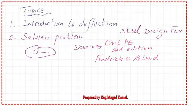
This is the content of the lecture. What are the deflection parameters?
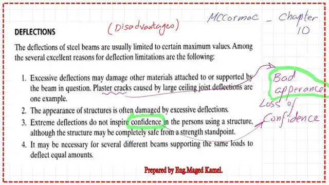
What are the disadvantages of the deflection of steel beams?
This is a quote from Prof. Mccormac’s book, chapter 10. One of the disadvantages of deflection is that it may damage other materials and create plaster cracks. Therefore, the deflection is usually limited to a maximum value since it
The deflection may damage other materials attached to or supported by the beam.
The second point is that structures are often damaged by excessive deflections, which give them a bad appearance.
The third point is loss of confidence due to the appearance of deflection for a building. The last point is that it may be necessary for several different beams supporting the same loads to deflect equal amounts for appearance purposes to be the same amount of deflection.
What are the parameters of the deflection of steel beams?
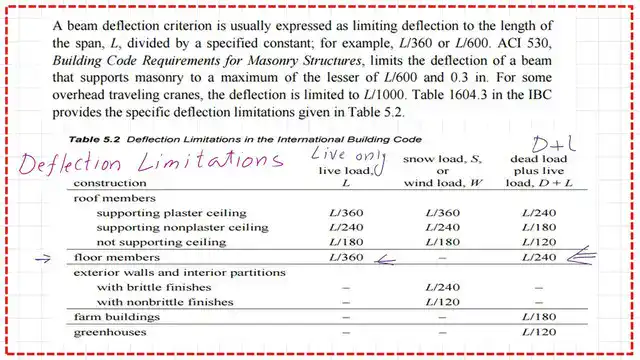
The live load deflections are approximately equal to L/360 of the span length. However, the reader should note that the limitation of the deflection of steel beams falls in the serviceability area.
Therefore, deflections are determined for the service loads, so we cannot use the Ultimate loads, such as the 1.2D+1.60L combination, to estimate the deflection.
What tools enable us to determine deflection? We use the moment area method, converting the area of moments into loads from which we estimate the shear forces, which gives us the value of the slope.
We can evaluate the deflection values from the bending produced from Moment loads and use the conjugate beam method, which converts the end cantilever portion into fixed support and the hinged end into hinged supports.

The third method is virtual work. The deflection value = 5WL^4/384*EI for a simply supported beam under uniform load.

IBC provision for deflection.
The IBC, the building international building code, in which the beam deflection values are grouped into three categories, was Quoted from Prof. Fredrick Roland’s book Steel Design for Civil P.E.
The first item is for the roof members: live load L& snow load S or wind load W. The third category is the dead load plus live load D+L for each category, roof members if supporting plaster ceilings, and the deflection value.
Deflection is permitted for live load L to equal L/360, where L is the span. For snow Load s or wind load W, the deflection equals L/360; for D+L, the deflection is L/240.
For Roof members supporting non-plaster ceilings, the deflection values increased and became L=L/240 for live load, while for snow Load or wind load W=L/240 for D+L, the deflection is L/180.
For floor members, we do not have snow loads.
The allowable deflection is permissible under Live Loads L =span/360, while for D+L loads, the deflection will be considered as ( span/240).
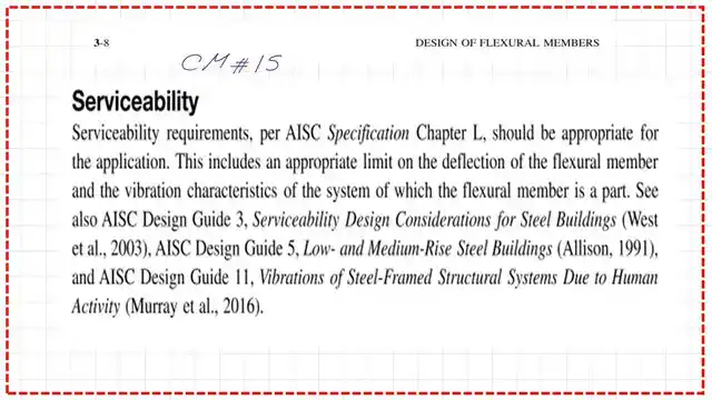
This is the provision of the AISC specification for Deflection based on serviceability.
What is factor C1 used in the deflection equation by AISC?
In the new section of the AISC, a new coefficient was given as a C1 factor to account for different loading conditions in various aspects. Four different steel beams have different c1 values. The deflection formula is expressed in terms of c1, the length of beam L, the maximum moment M, and the moment of inertia Ix. The modulus of elasticity E is substituted by the value of 29000 ksi in the formula.
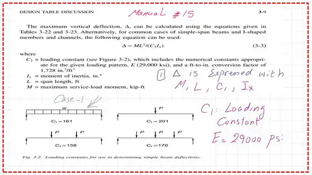
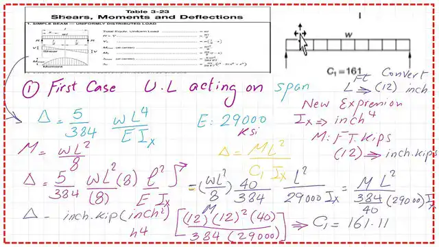
The value of C1 for a simply supported beam under Uniform load.
The known deflection equation for steel beam for a simply supported equals (5/384)*W*L^4/E*I.
The deflection equation is rewritten in terms of moment, considering moment equals w*L^2/8.The deflection equals 40/384*ML^2/EI. Substitute the value of E as equal to 29000 Ksi, and Convert M from Ft.kips to inch Kip by multiplying by 12. Convert L^2 from Ft^2 to inch2 by multiplying by 144.
The Term C1 as a denominator term equals (384*29000)/(40*(12)^3) and is estimated to be equal to 161. Please refer to the next slide image for details of the estimate.
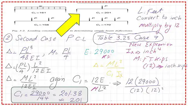
The value of C1 for a beam under concentrated load at the middle.
The known deflection equation for a steel beam simply supported under a central load is P*L3/48*EI. The maximum moment at the midpoint is P*L/4.
The deflection equation, rewritten in terms of the moment, equals ML^2/12*EI. Substitute the value of E as equal to 29000 Ksi, and Convert M from Ft.kips to inch Kip by multiplying by 12. Convert L2 from Ft2 to inch2 by multiplying by 144.
The Term C1 as a denominator term equals (12*29000)/(12)^3 and is estimated to equal 201. Please refer to the next slide image for details of the estimate.
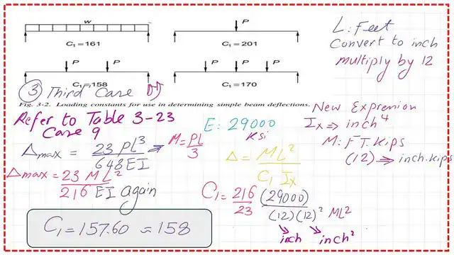
The value of C1 for a beam under two concentrated loads.
The known deflection equation for a steel beam simply supported under two concentrated loads is (23/648)*P*L3/EI. The maximum moment at the midpoint is P*L/3.
The deflection equation, rewritten in terms of the moment, equals (23/216)*M*L2/EI. Substitute the value of E as equal to 29000 Ksi, and Convert M from Ft.kips to inch Kip by multiplying by 12. Convert L2 from Ft2 to inch2 by multiplying by 144.
The Term C1 as a denominator term equals (216/23)*(29000)/(12)^3 and is estimated to equal 158. Please refer to the next slide image for details of the estimate.
The value of C1 for a beam under three concentrated loads.
First, we will estimate the maximum moment at the midpoint. As we can see from the next slide image, the M max equals 0.50Pl. The deflection value is quoted from table 3-22a-and equals 0.05*P*L3/EI.
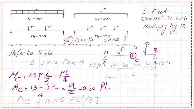
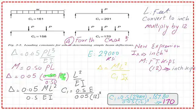
The deflection equation, rewritten in terms of the moment, equals (0.05/0.50)*M*L2/EI. Substitute the value of E as equal to 29000 Ksi, and Convert M from Ft.kips to inch Kip by multiplying by 12. Convert L2 from Ft2 to inch2 by multiplying by 144.
The Term C1 as a denominator term equals (0.50/0.05)*(29000)/(12)^3 and is estimated to equal 170. Please refer to the next slide image for details of the estimate.
We will continue the subject in the next two posts. A solved problem will be presented.
As an external resource for the deflection. Chapter 8 – Bending Members.
This link for the next post solved problem 5-1-part 1-2.