The First moment of area and product of inertia at the CG.
The expression of the first moment of area at the Cg.
We will proceed with our discussion of the first moment of area and pure bending. This is an isometric beam, though.
The Z-axis is oriented in the direction of the reader, the Y-axis is perpendicular to the X, and the X-axis is longitudinal. In the event where there is pure bending, as seen by the red arrow spinning about Z, we depict it in isometric form. For directions, please see the previous post.
Thus, we’ll refer to it as MZ and circle Z. Examining the transverse section reveals that the Z-axis is oriented to the left, and the Y is oriented vertically.
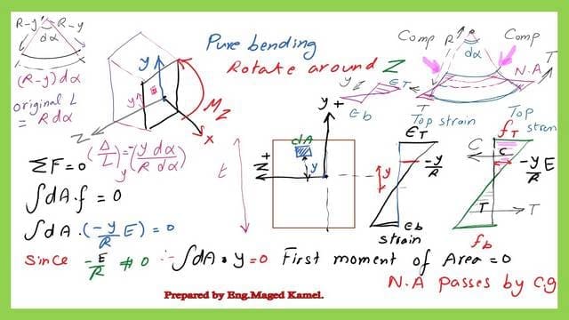


There is neither compression nor tension present because we are only experiencing pure bending.
Since there are no tension or compression forces across the section, the total of the forces for the strip dA, where the stress is equal to (-y*E/R), will equal zero. We will next perform the integration.
Since this stress =(-y*E/R)=0, we equal it to zero for the entirety of the segment. Furthermore, E over R cannot equal zero because it has a value.
y (-) sign will indicate that when y has a positive value we have a compression from the neutral axis to the uppermost part of the section; for the lower part, it will become positive when we multiply the strain by young modulus for Elasticity E we will give the stress value (+).
We will examine the small strip dA apart from the Z-axis by y distance by the expression, which we have obtained that the strain is (-y/R) at distance.


Thus, the integration of ∫y*dA would be the sole thing that would be regarded as equal to zero, and the first moment of area, which is an expression that is well-known to us, is the first moment of area concerning any section = 0, indicating that this section is passing by the C G.
The expression of the product of inertia at the Cg.
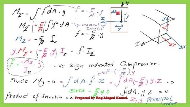
From that relationship, we get that the z-axis is passing by the centroid. We have a moment, and the moment value is the moment around Z. This moment value will be =∫f *dA*y.
We have the strip, the dA is apart by y, and the (f*dA) is the force (F*y) will give the moment we are going to make integration of these forces around Z.
We know that the stress equals (-y*E/R), so we replace the value of f in the M z equation as ∫f*dA*y, and we are left with ∫(-E/R) ∫(Y^2*dA).
We are familiar with the expression ∫ dA*y^2, which is the moment of inertia, but this time it is a moment of inertia around Z. We can write Mz. =-(E/R)*Iz. Again, the (-) sign will indicate this in the upper portion of the y; it is compression, and since (f=-E/R*y), we will multiply this left side by y.
.
And this right-hand side by y and looking to this (f=-E*y/R), we consider (f=-E*y/R). We have (y*Mz) = f*Iz.
We get a new expression for the stress due to pure bending, which is stress f=(-)Mz*y/Iz, and again, the negative sign indicates compression for the stress above the neutral axis.
The stress will become tension, and since we don’t have a bending moment around y, we can write that ∫dAfz=0, which is the product of the inertia expression.

How to express local and global access using SAP 2000? the next slide image shows axis 1-1 representing the global axis X for a horizontal member, while axis 2-2 is the minor axis for a cross-section and represents the Z-axis. The major axis 3-3 for the cross section represents the Y-axis.
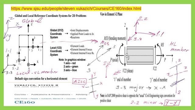

In the next slide image, we can see How to express local and global access using SAP 2000 for vertical elements.
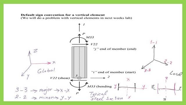

For more details please find the link to the CE 160 files which express in more detail the sap 2000.
This is the link for an external resource. Bending Equation Derivation
This is the link for the next post, Estimation of Max and Minimum Moment of Inertia for a section.

