
Last Updated on January 5, 2026 by Maged kamel
The theory of pure bending.
Lecture objectives.
Our first item is the theory of pure bending assumptions and the relation. The second point is why we estimate the product of inertia. The next topic we will discuss is Mohr’s circle of inertia and how it may be used to calculate the maximum and minimum values of the moment of inertia.

Assumptions to follow for the theory of pure bending.
First, we make some assumptions: when a beam is acted on by pure bending, it will be distorted.
But first, let’s look at the beam before deformation. We have two axes, X and Y, and we consider the beam’s section to be rectangular at the initial stage before deformation.
We have a section that is vertical and parallel to the neutral axis. The plain section that was parallel to the neutral axis before the deformation is thought to stay parallel to the neutral axis after the deformation.
Following deformation, the beam will take on a curved shape and will no longer be vertical perpendicularly. Nonetheless, the section will remain perpendicular to the neutral axis upon deformation.
The second assumption is that bending causes minimal deformation.
The third assumption is that the beam is initially straight, with all longitudinal filaments bending into a circular arc with a shared center of curvature.
one means that all of these perpendicular sections are in one section, and if we assume another section, it will be a plain section perpendicular to the neutral axis. The third part will be perpendicular to the neutral axis. If you expand all of these portions, they will also come together in the same place.
The line formed will be in the shape of a circular arc.

The fourth assumption of pure bending theory is that vertical deformation, or transverse strain (εyy), can be omitted.
Compression is always followed by compression or transverse strain. In our situation, the transverse strain (εyy=dh/h) will be negative. The longitudinal deformation will be equal to the expansion of length divided by the initial length.
In εyy, dl/l replaces length extension and is positive. We examine whether it has a small value and eliminate it.
The fifth assumption states that the radius of curvature is larger than the cross-sectional dimension. The sixth assumption states that Young’s modulus of elasticity in tension and compression will be the same.

Pure bending: what is it? Pure bending results in a shear value of 0 when the beam experiences moments on both sides that are equal.
Why will there be no shear value? Because there will be a pair produced by this bending moment on the right. The couple will be upward because of the anti-clockwise direction of the shear, which will also cause a downward shear force on the right side. At the same time, an anti-clockwise resisting couple will be produced.
As a result, the shear forces will be opposed to one another—downward for one and upward for the other—and they should cancel each other out.
For the bending moment diagram, the shear force will therefore equal zero. This is saggy if we wish to sketch it. Positively, value will be allocated to the appropriate assistance, and this will be closed. That’s this, left to right.
The beam will experience bending with a positive bending moment. The left- and right-side moments will cause the beam to bend into an arc, and, as the diagram shows, the enclosed angle between the two perpendicular lines will be α.
In the second scenario, which involves pure bending, you have a simply supported beam that is hinged and is being acted upon by two shear forces of equal value, P and P, which are operating on the beam’s third point, L/3, and L/3, respectively.
In the shear forces figure, we have P, a positive shear force that rises and falls until it reaches B, and a negative shear that moves from the right side to the left and closes at point d.
As we have a positive bending moment (P*L/3) for the bending moment, the intermediate section will have a bending moment with no shear force between C and d = 0. The pure bending moment is present in this second instance.

Stress formula for the case of pure bending.
The third supposition states that the beam is originally straight. As we can see, the section is rectangular, and the x- and y-axes were there before the deformation.
Consider a section where a distance y separates a small element before deformation, and the section’s distance apart is (dx).
Looking at the deformation, we observe that the beam would bend in this way, and the x, y, and perpendicular axis 3 all display the neutral axis, which was the horizontal neutral axis. Assuming that an enclosed arc angle (dα) is to be studied and that the arc radius is R.
After equating, we will determine the strain value before deformation.
Following deformation, there was no strain.
This section, whose length is (dx), will eventually become Rdα. When the element at Y distance up is deformed, its length becomes (R-Y) multiplied by (dα), when it was initially dx.
Thus, the length of this red line was initially dx, or (R-y*dα). It’s moving toward the neutral axis if we compare it.
Since nothing has changed, we can interpret the dx as =(Rdα), where the deformation is either compression or tension.
We are above the neutral axis in this instance. Thus, the distortion will turn negative.
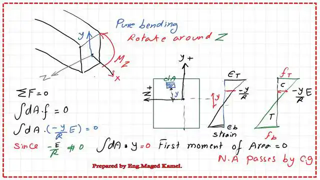
After subtracting +Rdα and -Rdα from (R-y)dα-Rdα, we are left with (-ydα). Given that a strain is a deformation across the original length, we may calculate its derivative as (-ydα) from the original length of R*dα. Consequently, we have (-y/R), and since stress/strain equals Young’s modulus of elasticity, our strain equals (-y)/R.
Since there is a strain, the strain * Young’s modulus of elasticity is given by the formula f= (e E). In other words, f=(-y/R)(E).

From assumption # 6, Young’s modulus of elasticity is the same for the case of tension and compression.
You can view or download the pdf data for this post.
This is a link to a useful external resource by Jus.
This is a link to the following post: Post 2: 2-First moment of area and product of inertia at the CG.