Buckling for columns-effective length factors
What is buckling?
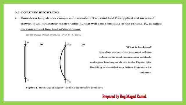
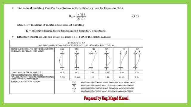
Buckling is identified as a failure limit state, the shape of failure for that column. we recall our equation as Pcr =π^2 EI/(KL)^2, the coefficient k value is given as per the shown table based on the AISC code


Here are the different shapes, if it is fixed from both sides the actual distance will be from the inflection point to another inflection point.
First, what is the cause of buckling? buckling occurs when a straight column acted upon by compression force it will be converted to another form having a bending moment as shown in Figure 1b, it was plumbed later to the deformed shape


Effective Length for columns.
Effective Length (K) Factor Explained:
The K factor approximates the length that a column concrete columns, aluminum columns, etc. All use the effective length factor) actually buckles. The effective length can be longer, shorter, or exactly the actual length depending on the rigidity of the supports. In practice, if the K factor is below 1.0 then the structure is braced (the structure has a greater ability to deal with any lateral forces) and if the structure is above 1.0 then the structure is unbraced (the structure has a lesser ability to deal with any lateral forces).
AISC code provision for the effective length table.
The AISC code has specified 6 cases for the effective length of columns as shown in the next slide.
1-Case:1- Column is fixed from both sides. The effective length factor k value =0.50 but the recommended value for K is set to be=0.65.
2-Case:2- Column is hinged from one side and hinged from the other side. The effective length factor k value =0.70 but the recommended value is set to be=0.80.
3-Case:3- Column is fixed from one side rotation fixed and translation free from the other side. The effective length factor k value =1.0 but the recommended value is set to be=1.20.
4-Case:4- The column is hinged from two sides. The effective length factor k value =1.0 but the recommended value is set to be=1.00.
5-Case:5- Column is fixed from one side and free from the other side. The effective length factor k value =1.0 also the recommended value is set to be=1.00.
6-Case:6- Column is hinged from one side rotation fixed and translation free from the other side. The effective length factor k value =21.0 also the recommended value is set to be=2.00.

The difference between local buckling and general buckling.
To differentiate between local and general buckling, the figures in front of us that general Buckling occurs when a column is under compressive force from both ends is a general Buckling for the whole column.
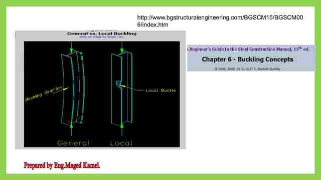

Local buckling, from its name, occurs for a portion of the column as in the right figure.
The next image shows the k factor is based on the distance between the inflection points.
The definition is important for both the strong and weak axis, For a w section, the moment of inertia about the x-axis is much higher as compared to the inertia in the y-direction. The x-axis is called the strong axis, while the y-axis is called the weak axis the figures on the left express. The distance between the inflection points For the three cases the root of curvature has changed at a point that is why it is called the point of inflection due to inflection the distance becomes smaller as K*L=0.5 L.
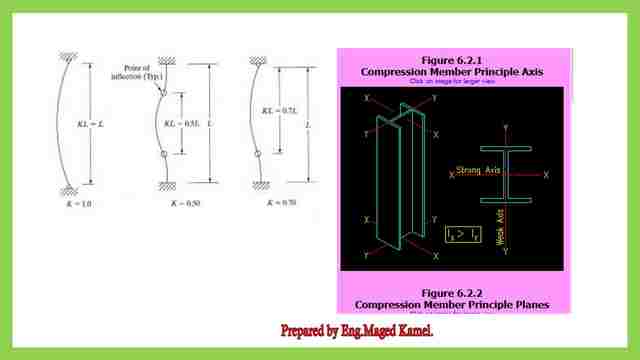

The next image shows the difference between buckling about the major axis and buckling about the minor axis.
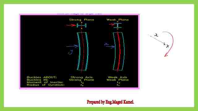

Imagine that you have a curved bow and an arrow, if we have to buckle about the major axis then our pointed arrow direction is perpendicular to the major axis in the x-direction, that major axis has a bigger value of inertia, on the contrary.
If we have to buckle about the minor axis, with a smaller value of inertia, then our arrow is pointing to the direction that is perpendicular to the y-direction.
This is the pdf file used in the illustration of this post and the next post.
The next post: Buckling for columns-part 2.
For a good reference from Prof. T. Bart Quimby, P.E., Ph.D., F.ASCE, refer to this link for public concepts.

