A Solved problem 5-7 for block shear.
A Solved problem 5-7 for Block shear.
Topics included in our discussion are shown in the next slides. This is a list of the Block shear Equations by the code provision J4-5.
The provision is used to calculate the block shear strength for any plane.


Introduction to the solved problem 5-7 for block shear of tension member connected to a gusset plate through bolted connections, the types of modes of failures are shown from mode b to mode d.
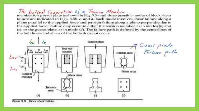

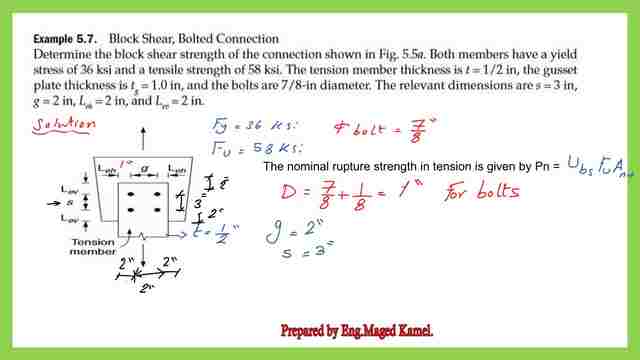
Example 5-7, from Prof. Alan Williams’s book, states that for the tension member connected to a guest plate, the thickness of the tension member is 1/2 inch, while the thickness of the gusset plate is 1″.
It is required to determine the block shear capacity for that hanging rod. The steps are as follows:
1: The diameter for each bolt D will be 7/8+1/8=1″. We add 1/8″ to compensate for drilling and occurring damage.
2: The abbreviation g is the gauge distance, which is the perpendicular distance to the tension load, here is the horizontal distance=2″ as given, while, s, is the pitch distance in the direction of the load=3″.

A Solved problem 5-7 for block shear, an inspection of mode b.
3: We have one plane subjected to tension and two planes subjected to shear.
4: The net area for tension Ant=Agross-2*halves of bolts*t plate,
so=Ant=2*1/2-(2*1/2*1/2)=1/2 inch2, while Agt=Agross=2*1/2=1 inch2.
5: For the two areas subjected to shear, we have Agv=2*(5)*1/2=5 inch; for Anv, we
have to deduct 2 dimeters + 2 1/2 diameters = 3 inches.
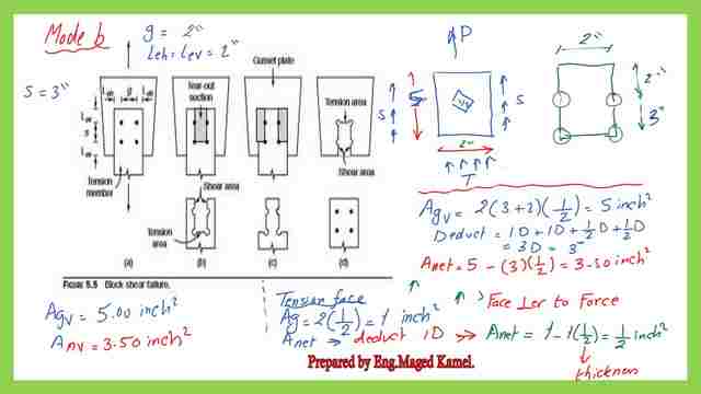

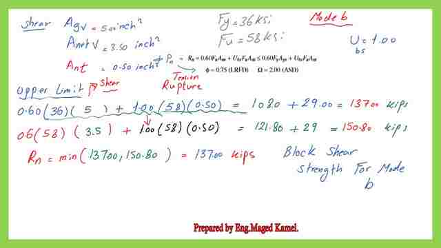
6: The gross area for shear Agv=2*5*1/2=5 inch2, Anv=5-(3*1*1/2)=3.50 inch2.
Fu=58 ksi, fy=36 ksi, Anv=3.50 inch2, UBs=1.0, Ant=1/2 inch2. For the LHS we have the nominal load equal to 0.6*58*3.50+1*58*0.50=150.8 kips.
While for the RHS, we have: the nominal load equal to (0.60*36*5+1.0*58*0.50=137.0 kips, for Rn it is the minimum value of(150.80,137)=137.0 kips.

A Solved problem 5-7 for block shear, an inspection of mode c.
We continue with the solved problem 5-7 for block shear. We have two planes subjected to tension and two planes subjected to shear.
Consider one plane, the net area for tension Ant=Agross-1*half of the bolts*t plate. then we multiply later on by 2.
Ant=2*1/2-(1*1/2*1/2)=1-1/4=0.75 inch2, then finally Ant=2*0.75=1.50 inch2, while Agt=Agross=2*1/2*2=2 inch2.
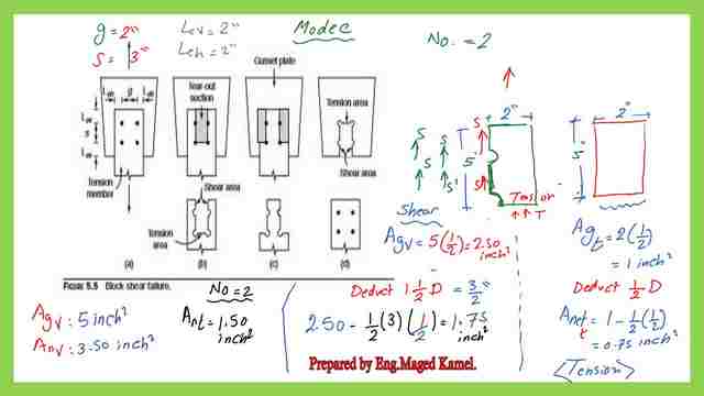

For the two areas subjected to shear, we have Agv=2*((5)*1/2)=5 inch2, for Anv, we have to deduct 2 dimeters +2 1/2 diameters=3 diameters=5-(3*1*1/2)=3.50 inch. Agv=5 inch2, Anv=3.50 inch2. This is the equation for which we will substitute for mode C.


Fu=58 ksi, fy=36 ksi, Anv=3.50 inch2, UBs=1.0, Ant=1.50 inch2. The gross area for shear Agv=5.0 inch2, while the net area for shear Anv=3.50 inch2.
For the LHS=0.6*58*3.50+1*58*1.50=208.80 kips, while the RHS=0.60*36*5+1*58*1.50=195.0 kips, for Rn it is the minimum value of(208.80,195.0)=195.0 kips.
Solved problem 5-7 for block shear, and an inspection of mode d.
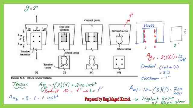
We continue with the solved problem 5-7 for block shear, we have one plane which is subjected to tension, and two planes subjected to shear, in the gusset plate which is 1″ thick.
The net area for tension Ant=Agross-2*half of bolts*t plate, so=Ant=2*1-(2*1/2*1)=2-1=1 inch2, then finally Agt=2.0 inch2, while Ant=1 inch2.
For the two areas subjected to shear, we have Agv=2*((5)*1)=10 inch2, for Anv, we have to deduct 3 dimeters Anv=10-(3*1*1)=7.0 inch. The Agv=10 inch2, while Anv=7 inch2.
Since these values are very high as compared to the two previous modes b&c, we will not proceed to estimate the Rn value.

The final answer will indicate that failure will occur first based on mode b since it gives the smallest Rn out of the three failure modes b,c, d, which is 137.0 kips, while for mode c Rn=195.0 kips.
Again for the LRFD, we will multiply by Phi=0.75, Φ*Rn=0.75*137=102.75 kips for the LRFD, while for the ASD, we have Ω=2.0 then 1/Ω*Rn=(1/2)*137.0=68.50 kips.


This is the PDF used in the illustration of this post.
This is the previous post#13, The relation between Block shear and coped beams. Please refer to this link.
The next post is problem 3-7 for staggered bolts.
Very useful external link Shear Rupture for a more detailed illustration of block shear. A Beginner’s Guide to the Steel Construction Manual, 14th ed.

