Last Updated on February 14, 2026 by Maged kamel
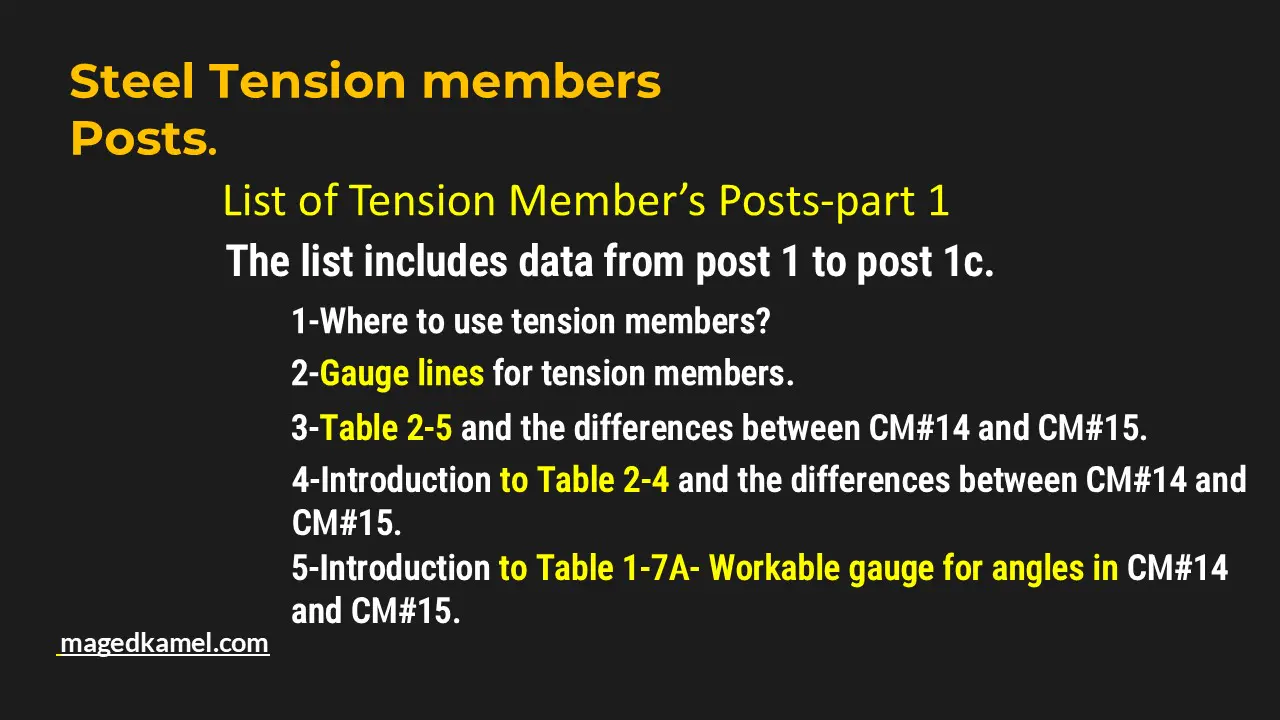
List of Tension Member’s Posts-part 1
Welcome to the first part of our comprehensive guide on Tension Members. This section will cover topics ranging from the basics to advanced applications and design considerations.
A step-by-step introduction to Tension members.
Understanding tension members is essential for any structural engineer. They are critical components used in construction to support loads and resist tensile forces.
Tension members are often used in truss structures where they connect load-bearing elements. For example, in a roof truss, tension members help distribute weight evenly.
The net and gross areas are fundamental concepts in tension member design. After accounting for fastener holes, the net area signifies the effective cross-section, while the gross area represents the total cross-section before deductions.
The second item is the AISC chapter governing tension member design, which includes specific guidelines to enhance safety and performance. Understanding these guidelines is crucial, as they cover factors like material selection and load calculations.
This is the first post of the Tension Member’s Posts, which includes the following items; the first item includes: where to use the tension members?
The second item: What is the chapter in the AISC that governs the design of tension members?
The third item is the net area and gross area. The net area is the section area from which the fastener areas are deducted. Fasteners include bolts and rivets.
Additionally, I have added three more insightful posts that delve deeper into the nuances of tension members, including their design methodology and material properties.
Post 1A will cover a simplified introduction to tension members. Beginners must grasp these concepts before delving into more complex topics.
Post 1B will focus on a detailed review of AISC Table 2-5, highlighting differences among various construction manuals. This comparison is invaluable for understanding updates in building codes.

Here is the link to post 1: A step-by-step introduction to Tension members.
I added three more posts: 1a& 1b, and 1C.
Post 1A-easy introduction to tension members- Part 2.
Post 1a- Easy introduction to Tension members-part-2. The post discusses Table 2-4 based on CM#14.

Post-1 b-review of AISC Table 2-5 for plates.
Post 1b includes the differences between construction manuals CM#14 and CM#15 for AISC Table 2-5.

Post 1C will thoroughly illustrate AISC Table 2-4, detailing the ASTM specifications for different structural shapes, ensuring a clear understanding of material choices.


This section will also explore real-world applications and examples of tension members to deepen understanding of their impact on structural integrity.
I have added a review of Table 1-7a for workable gauge lines for angle legs between CM#14 and CM#15.

For more insights, visit our extensive list of Tension Members’ Posts in Part 2, which covers additional topics to enhance your understanding.
Post 1C-Best and Full Illustration of AISC Table 2-4.
Post 1C discusses Table 2-4, which is included in the construction manuals CM #14 and 15. Table 2-4 lists the applicable ASTM specifications for various structural shapes, excluding plates and sheets.
I introduced the conversion factor between Imperial units and SI units.
I introduced Table A3.1, which lists materials based on the new specification and CM#16.
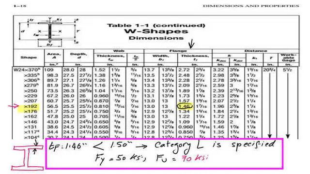
A solved problem for a W24x192 of A242, based on CM#14, is to find the yield and ultimate stresses for the given W section. We need to check the flange dimensions for the given W24x192. If it is <1.50 inches, it is considered type L, for which Fy=50 lsi and Fu=70 ksi.Please refer to the following slide image.
This is a link to the list of tension members’ posts in part 2.
An external source for tension members from Prof. T. Bartlett Quimby’s site, which is the Tension Member Overview based on CM#15.
An external source for tension members from Prof. T. Bartlett Quimby’s site, which is the Tension Member Overview