
Last Updated on September 15, 2026 by Maged kamel
List of Steel Beam Posts Part 4a
Solved Problem 10-1-Design Of Steel Section For Continuous Beam Part-1/4.
This is the 38th Post in the Steel Beam Posts-part-4a series, which includes solved problem 10-1 for a given continuous Beam. Select the lightest available W-section using plastic analysis, assuming full lateral support for both flanges.
Two methods are used: the first is the statistical (lower-bound) method, and the second is the mechanism (upper-bound) method. Both methods yield the same results.
The following slide shows how we can obtain the Ultimate loads for the given first-end Beam.
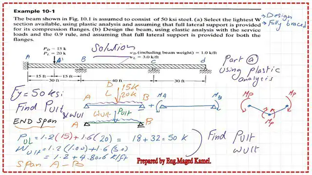
In part 1 of 4, we provide a detailed estimate of the plastic Moment for the first-end span AB.
This is the Link for Post 38: Solved problem 10-1 for Design of Steel Section for Continuous Beam – Part-1/4.
You can view or download the content of Post 38 as a PDF document by clicking the following button.
Solved problem 10-1-design of steel continuous Beam-2/4.
This is Post 38a, one of the Steel Beam Posts (part 4a), which explains how to derive a general Expression for the Moment values of a continuous Beam using the three-moment equations. This is the second part of the solved problem 10-1. In part 2 of 4, we provide a detailed estimate of the plastic Moment for the middle and end spans.
The following slide image shows the Plastic Moment Value for the middle Beam BC.

After estimating the plastic Moment, we select the maximum Value (466 ft-kips) as the nominal Moment and determine the plastic section Modulus—the Value of Zx=159.84 inch3. The section suitable for the Beam is W21x68, with a Zx Value of 160 in³, which is larger than the required Zx.
We can design the continuous Beam using LRFD. The following slide shows the detailed Beam design.

This is the Link for Post 38a: Solved problem 10-1-design of steel continuous Beam –Part 2/4
You can view or download the content of Post 38a as a PDF document by clicking the following button.
39-Solved problem 10-1-use three-moment equations 3/4.
This is the 39th Post of the Steel Beam Posts-part series-4a, whiexplainsdes how to derive a generalExpressionn for theMomentt valuinfor a continuousBeamm using the three-moment equations. This is the third part of the solved problem 10-1—a step-by-step guide to using the three-moment equation.
The following slide shows how to write the three-moment equation at point A and how we use matrices to relate Moment values to loads.

This is the Link for Post 39-39: Solved problem 10-1-use three-moment equations 3/4.
You can view or download the content of Post 39 as a PDF document by clicking the following button.
40-Solved problem 10-1-design of steel sections 4/4.
This is the 40th Post of the Steel Beam Posts-part-4, which includes the design of the Beam, using elastic analysis with service loads and the 0.90 rule, and assuming full lateral support is provided for both flanges.
This is the fourth part of the solved problem 10-1. The next slide image shows the final bending Moment diagram after applying the 0.90 rule, which reduces the negative moments at the supports. This redistribution is done by adding moments to the existing dead loads. The maximum positive Value is 345 Ft-Kips, and the maximum negative Value is 455 ft-kips. We select a W24x76, and the section has a Zx Value of 182.36 in^3.
This Post illustrates the detailed ASD design.

The following slide image shows the detailed design of the continuous Beam based on ASD. We use Table 3-2, where Zx values arrange sections. The selected Beam section is W24x76, which carries a Moment of 499 ft-kips, which is larger than the estimated maximum of 455 ft-kips.

This Links to Post 40 – Easy Design of Steel Section for Continuous Beam-4-4.
You can view or download the content of Post 40 as a PDF document by clicking the following button.
Here is the Link to Chapter 8 – Bending Members, section, A Beginner’s Guide to the Steel Construction Manual, 14th ed.
Here is the Link to Chapter 8 – Bending Members, section, A Beginner’s Guide to the Steel Construction Manual, 15th ed.
Here is the Link to Chapter 8 – Bending Members, section, A Beginner’s Guide to the Steel Construction Manual, 16th ed.