Last Updated on November 28, 2025 by Maged kamel
Available Strength for slender W section-CM#15.
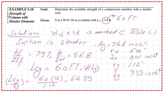
We will solve problems 5-10 that have already been addressed based on CM#14 in the previous two posts: Post 16 and Post 16a. From the unified design of steel structure, for local buckling, our steel section for the column is a W16x26 section. Kl at y direction =6.00 ft. The solution is based on CM#15, AISC-360-16. I have chosen a height of 6 feet to check our estimate with Table 6-1.
It is required to determine the available strength of a compression member with a slender web. The section is W16x26 as a column with lcy =6.0 ft.
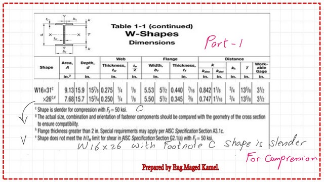
Check whether the column is slender or not. From Table 1-1, we have a C note, which indicates that the column W16x26 is slender. From the same table, we record the values of Ix, rx, Iy, and ry. The lc/ry value is equal to (6×12/1.12)=64.29. Please refer to the following slide image for more details.
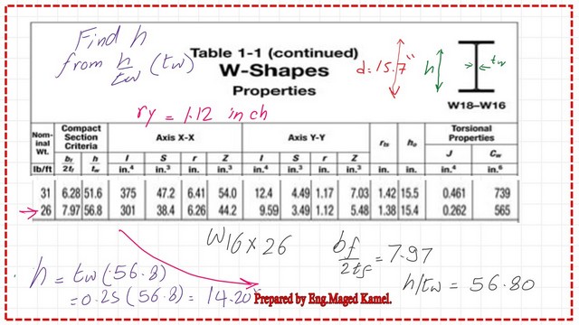
In the next two slides. We can see the full details of the W16x26 from Table 1-1.
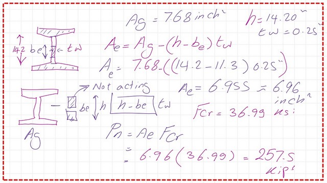
It is essential to find the web height h. We use the ratio h/t and then multiply it by t, which is the web thickness. The web height equals 14.20 inches.
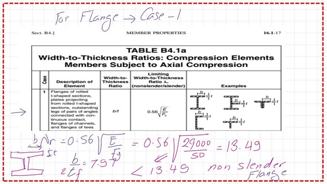
Is a column slender or not?
We will check against the value of 0.56*sqrt(E/fy), which yields 13.49 > bf/2tf for the flange in problem 5-10, indicating that the flange is non-slender.
While the value for W16x26, the ratio of (hw/tw) = 56.80, is given in the table, the limiting value is 1.49*sqrt(E/fy), which yields 33.72. This value is less than 56.80, so the section is a slender-web section.
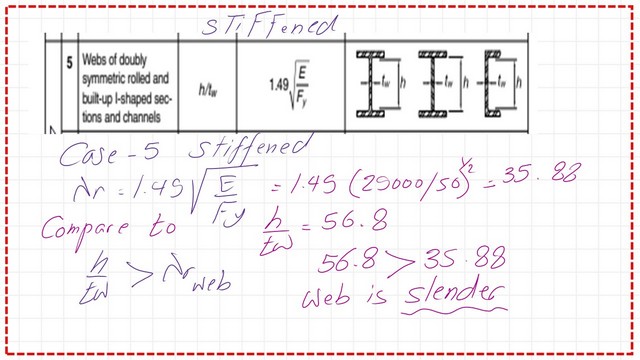
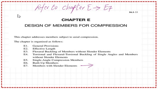
For the relevant data on slender columns, we refer to Chapter E, titled “Design of Members for Compression.” We check section E7 for members with slender elements.
What are the sections in code for slender members?
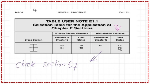
Chapter E is the Chapter that covers the Design of members for compression’ for slender members we refer to section E-7. Please refer to the next two slide images.
Based on the cross-section, refer to Section E7 in the specification for more information on the relevant equations and different terms related to slender W sections.
Fcr value for the column.
Step 4: Estimate λ2, which is Fy/FE, and obtain the relevant Fcr. Consider Q=1, where Q is the reduction factor, Fe value=99.73 ksi, while Fy=50 ksi.
λ2=(50/99.73)=0.50, we will evaluate Fcr by using the equation fcr=0.658^(λ2Q)(Q*Fy).

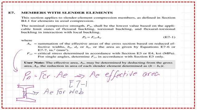
The following slide image shows the equation for the Nominal load of slender compression members, which equals the product of the effective area and the critical stress.
There are two conditions based on the value of h/tw, whether it is smaller or larger than Lambdar*sqrt(Fy/Fcr), which indicate whether we need to revise the web height or keep the same value.
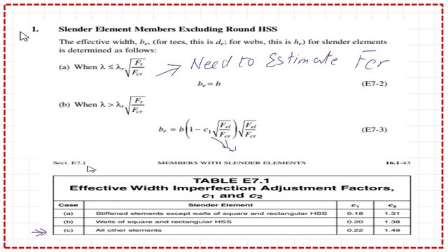
Check whether column is inelastic or not.
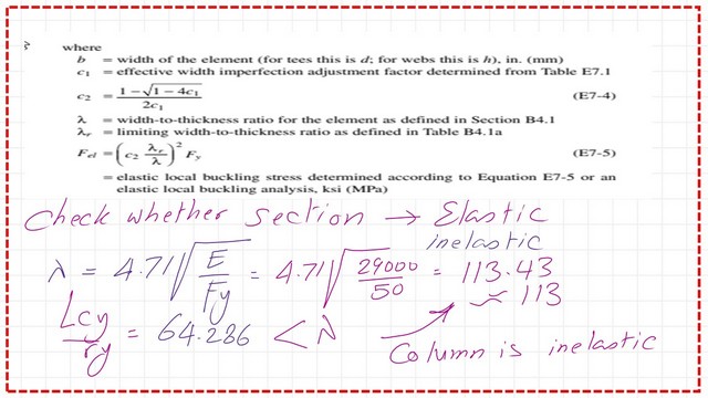
The following slide illustrates the various terms used to determine the effective web length. We will check whether the column is inelastic, by comparing the controlling lambda value of 113.43 with the actual Le/ry of the column, which equals 64.286. Since Le/ry is less than 113.43, the column is inelastic.
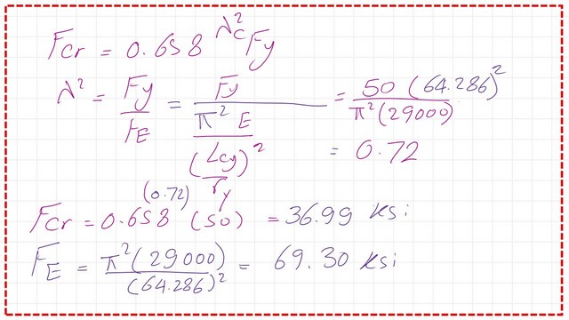
We estimate the critical stress of the column based on the value of λ^2. The Fcr value equals 36.99 ksi, and the Euler stress equals 69.30 ksi. Please refer to the next slide image..
How to estimate the effective web length?
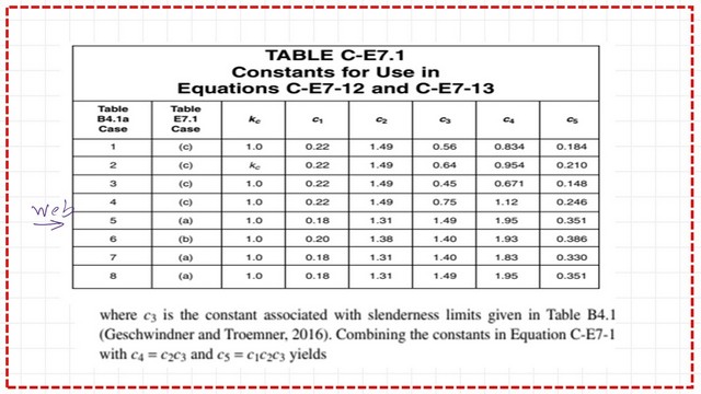
The controlling lambda for the web ratio is changed to c3*sqrt(E/Fy, instead of 1.49*sqrt(E/Fy based on Table 4.1a, since Fcr will govern the stress.
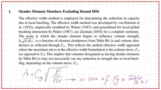
The following slide image shows the controlling factor C3, which equals 1.49, the same value as the Web factor in Table B4.1a.
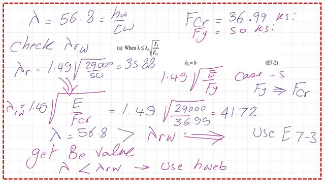
To determine whether to use the height of the web unchanged in our calculation of the effective area, we need to find the controlling lambda ratio, which equals 1.49*sqrt(29.3/36.99) = 1.49*sqrt (0.809/1.01) = 41.72. Since this ratio is less than h/tw, we need to modify the web height.
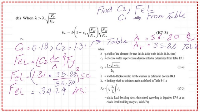
We need to estimate the Fel, or the elastic local buckling stress, which is a function of C1, C2, Fy, λ, and λ̄. The final value, as shown from the following slide image, equals 34.24 ksi.
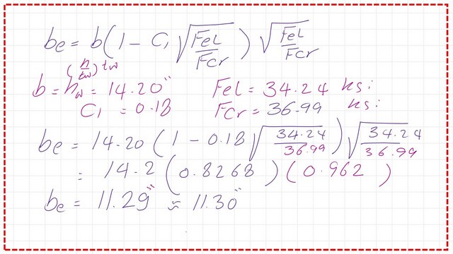
The following slide shows the detailed estimate of the effective web length.
The following slide shows the detailed estimate of the effective web area and how we can get the Nominal Load..
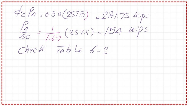
Estimate the Strength value for the column as LRFD value =Φc*Pn=Φc*Pn=0.90*257.5=231.75 kips. For the ASD value, Pn/Ω = 7.257.5/1.67 = 154.0 kips.
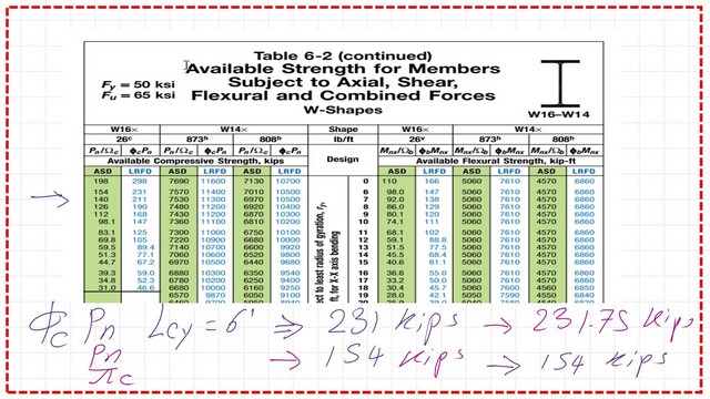
We can compare our estimated factored Loads with the values included for W16x26 for a column of ley=6 Ft. These values are very close to our estimated values.Thanks a lot.
This is the next post, Alignment chart part 2.
This is a link to a handy external link Chapter 7 – Concentrically Loaded Compression Members.