
Last Updated on October 5, 2026 by Maged kamel
- Mohr's Circle of Inertia- Second Case.
- Post content.
- Mohr's Circle of Inertia- second case.
- What is the orientation of the principal axes for Mohr's Circle of Inertia (second case)?
- The steps used to draw Mohr's Circle of Inertia in the second case.
- Need for two mirror points A' and B' in Mohr's Circle of Inertia, second case.
- The direction of the U and V axes in Mohr's Circle of inertia-second case.
Mohr’s Circle of Inertia- Second Case.
Post content.
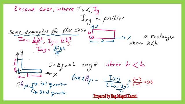
In this Post, we will discuss Mohr’s Circle of Inertia, the second case. Mohr’s Circle of inertia-second case is the case where the Moment of Inertia about the x-axis is less than the Moment of Inertia about the y-axis, and the Product of Inertia Ixy is positive.
Mohr’s Circle for the inertia-second case is shown as an example in two cases. The first case is a Rectangle with a height less than the width. The Value of the Moment of Inertia about the x-axis and the Y-axis, together with the Value of the Product of Inertia about the left corner, is included in the next slide image.
Mohr’s Circle of Inertia- second case.
Mohr’s Circle of inertia-second case is the case of Inertia about the left corner of the unequal angle of dimensions (b,h).
What is the orientation of the principal axes for Mohr’s Circle of Inertia (second case)?
We have the general Expression for the Moment of Inertia for any oriented axis, which we call Ix’. For Mohr’s Circle of the inertia-second case, the Value can be a maximum when cos (2θ) is negative and sin (2θ) is also negative; this angle is called 2φp1 or (2θp1). This angle is measured from the x-axis.
The other orthogonal direction, at an angle of 2φp2 (or 2θp2), is also measured from the x-axis, but this angle has positive cosine and sine values. The angle 2θp1 will lie in the third quadrant.
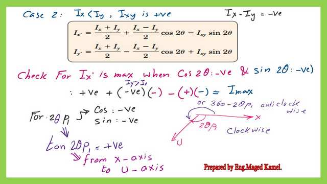
This is the case where Ix’ is minimal, when 2θp2 is located in the first quadrant.

How do I get the U and V directions for the normal view? By rotating the x-axis clockwise by 2θp1?

The steps used to draw Mohr’s Circle of Inertia in the second case.
The first two steps are to draw the two orthogonal axes. The first axis represents the Moment of Inertia values, Ix, Iy, and Imax, and the minimum values, while the second axis represents the values of the Product of Inertia, Ixy.
The coordinates of Point A (Ix) are given. Point B has coordinates (Iy,- Ixy), and Ixy is the positive Value of Ixy for Point A. Locate Points A and B with their respective Ix and Iy values, as shown in the next slide image.

Join Points A and B to get the Midpoint of line AB. This Point is the Circle’s center.
The radius Value is the sqrt( (Iy-Ix/2)^2+Ixy^2).
Start at Point O and draw a Circle with an estimated radius. The Circle will intersect the line at two points, C and E.
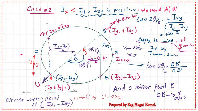
Angle 2θp1 is the angle between the X-axis and the Major axis U, which is the angle enclosed between OA and Line OE. Point E is the Point of maximum Inertia.
Angle 2θp2 is the angle between the x-axis and the minor axis V, which is the angle enclosed between OA and Line OC. Point C is the Point of the minimum Value of Inertia.
The distance from the vertical axis Ixy to Point C gives the Minimum Value of Inertia. In contrast, the distance from the same axis to Point E gives the maximum Value of Inertia.
Need for two mirror points A’ and B’ in Mohr’s Circle of Inertia, second case.
In the normal view, the x-axis is horizontal, whereas in Mohr’s Circle for the inertia-second case, it is oriented at an angle of 2φp1 from the U-direction. We need a mirror Point A’ to let the x-direction in Mohr’s Circle of the inertia-second case be a horizontal line.

Set Point A’, the mirror of Point A, with coordinates (Ix, -Ixy), which gives the direction of the maximum Moment axis U. This Point A’ lets us rotate the x-axis, or line OA, clockwise by 2θp1. The x-axis will be horizontal, and the U line will also have a new direction represented by line OA’.
Point B’ is the mirror of Point B and has coordinates (Iy,+Ixy) and is used to indicate the direction of the V-axis, which is the direction of the minimum Moment of Inertia axis.
From the relation for tan 2φp, we get a positive tangent Value, which means the V-axis has an enclosed angle measured anticlockwise.
The direction of the U and V axes in Mohr’s Circle of inertia-second case.
Join points OA’ to get the U-direction. Join the two points O and B’ to get the V-direction. The directions of both the U and V axes are shown in the next slide image.
The V axis is rotated by an angle of (θp2) anticlockwise from axis X, while the U axis is rotated by an angle of (φθ1) clockwise from axis X in the standard view.
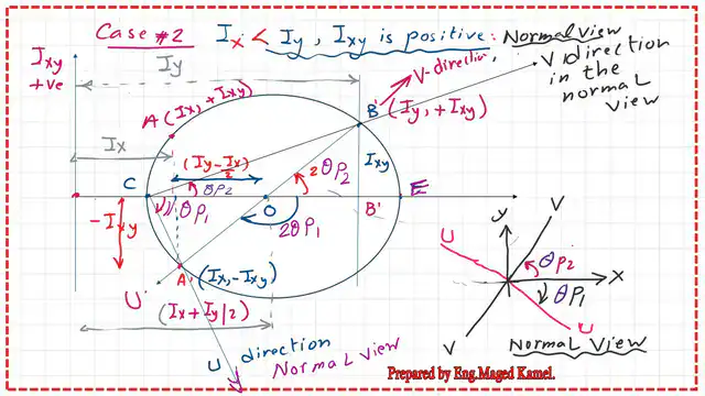
For the orientation of two axes, with the x-axis horizontal, Point E is where x’ = Ix at 2θ = zero and Ix’y’ = +Ixy, since this is horizontal, while Point A’ IxIxIx’ = Iy and =- Ixy =- Ixy.
The line OA’ is the direction of U. This line has an angle equal to ( -2θp1) measured from the horizontal line OE. The line OB’ is the direction of V. This line has an angle equal to (+2θp2) measured from the horizontal line OE in an anticlockwise direction.

You can view or download the PDF for this Post by clicking the button below.
In the next Post, we will introduce a problem on Mohr’s Circle, case 2.
This is a Link to a useful external resource—a calculator for cross-section, Mass, Axial and Polar Area Moment of Inertia, and Section Modulus.