Last Updated on October 25, 2025 by Maged kamel
Video that illustrates the content of the post.
A solved problem 5-1 for the elastic and plastic Moduli.
In the solved problem 5-1, a built-up shape is given. The top and bottom flange widths are 8 inches, and their thicknesses are equal to “1”. The web height is 1 foot, and its thickness is 1/2 inch. The following steps in the next two slides are required for part a.
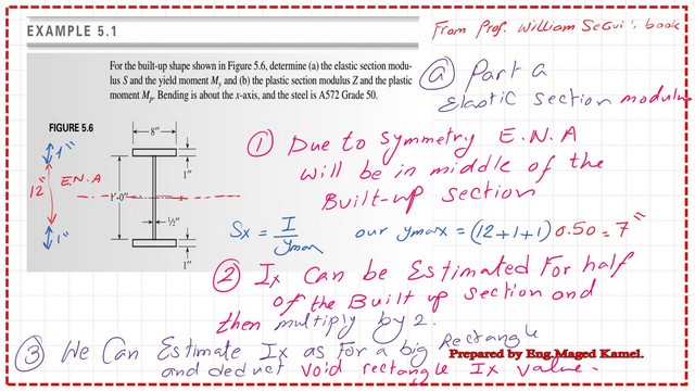
The first requirement is to get the elastic section modulus Sx=Ix/y, where Sx is the elastic section modulus, Ix is the moment of inertia about the x-axis, and y is the distance from the Elastic neutral axis to the upper fiber, which is =Ix/y max.
We have converted the inner height of 1 ft =12″. For the Ymax=1/2(overall depth)=1/2*(12+1+1)=7″.
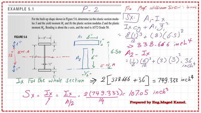
Ix of the built-up section =sum of (Ix upper plate + Ix web + Ix of the lower plate); due to symmetry, it can be rewritten as Ix=2*(Ix-upper plate at the Cg + Ix-web at CG).
The Ix value =749.33 inch4; please refer to the next slide for more details of the calculations. Sx=Ix/y max, since Ix=749.333 inch4 and y max=7″, then Sx=749.333/7=107.05 inch3.
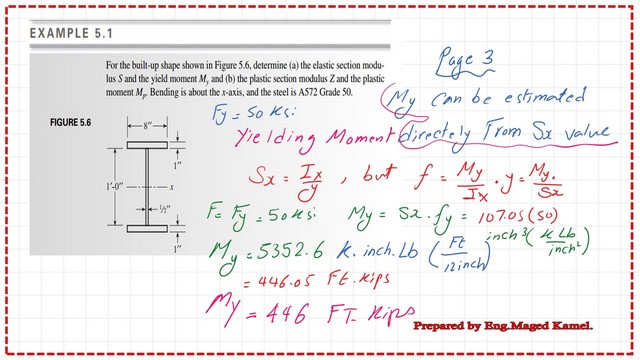
The second requirement is yield moment My, which is My=Sx*Fy. Based on the steel section’s material, ASTM A572 grade 50, the yield stress Fy=50 ksi.
The yield moment My=107.0*50=5352.0 inch. Kips. To convert to ft-kips, we will divide by/12—finally, the yield moment My=446 ft-kips. The details of the calculations are shown in the next slide image.
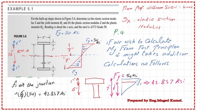
How do we evaluate the yielding moment of a section using the first principles?
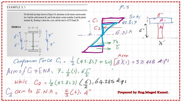
We can get the value of the yield moment My from the first principles by drawing a stress diagram, for which Fy=50 ksi, as shown in the next slide image.
We equate the tension and compression forces as C=T=(1/2)Fy*(h/2), y ct is the arm distance between the compression force C and the tension Force T, we call it yct=h-(2/6)h=2/3*h.

The compression force can be estimated as the sum of two compressive forces, C1 and C2, where C1 is the force acting due to the trapezium stress distribution. At the same time, C2 is the force acting due to the triangular stress distribution portion.
C1 = 371.428 kips, while C2 = 64.285 kips. The following slide image shows each force’s application distance from the neutral axis.
A tabulation of the compression forces and Tension forces is shown. C1 is the force acting on the Upper plate, and C2 is the compression force acting on the middle web for a height of 8″. The corresponding tensile forces T1 and T2 are included.
We can estimate the Yield moment value for the solved problem 5-1 by summing the two moments due to C1, T1, and C2 and T2 forces.
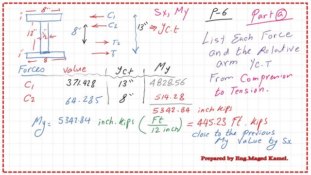
Please find the PDF file for part a, of the solved problem 5-1.
How do we evaluate Zx for part b of solved problems 5-1?
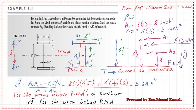
To evaluate the plastic section modulus Zx, we must determine AT/2, half of the total area, and find the axis that divides the whole section equally. Due to the symmetry of the built-up section, we will get the P.N.A at 7″ from the bottom, thus coinciding with the elastic neutral axis previously estimated.
We get the y bar for At/2, half of the total area about the P.N.A., and estimate its value from the first-moment area.
The plastic section modulus can be estimated as Zx=AT/2*(ybar1+y2); the full calculation is shown in the next slide.
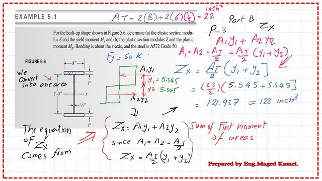
How do we evaluate MP for part b of solved problem 5-1?
The plastic moment equation is Mp=Zx*Fy, the plastic moment can be estimated as the product of Zx by the yield stress Fy.Zx=121.957 inch3, while the yield stress Fy=50 ksi. The final estimated value is shown in the next slide. The MP value for solved problem 5-1 is 508.0 ft. kips.
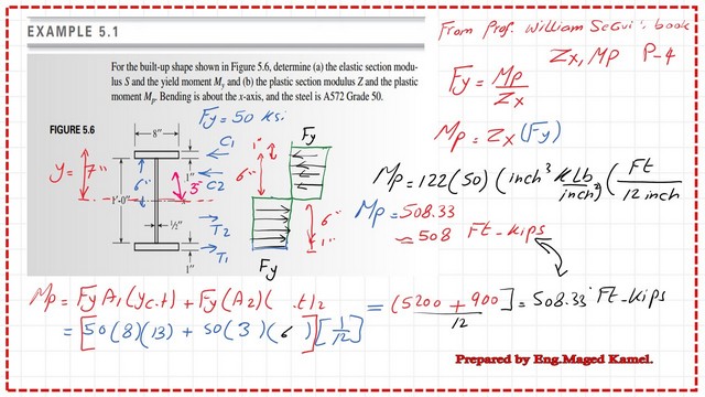
Please find the PDF file for part b, of the solved problem 5-1.
For the buckling concept, please refer to the link from Prof. T. Bart Quimby, P.E., Ph.D., F.ASCE.
This is a link to the next post, Which Solves problem 5-2 for Sx&Zx and the shape factor.