Last Updated on July 27, 2025 by Maged kamel
A Solved Problem 4-9 For available compressive strength.
This is a summary of the content of post 5- compression.
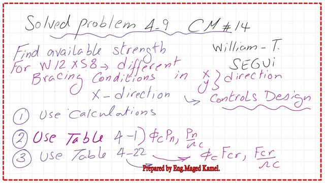
A solved problem 4-9 for critical stress for a given W-section.
We are continuing with the strength-solved problems for compression members and how to use tables to get the value for LRFD and ASD.
Now with a new solved problem, problem 4-9 from Prof Segui’s handbook. We have a W12x 58, height is 24 feet long, is pinned at both ends and braced in the weak direction at the third point, in the x-direction, the column is braced at the top and bottom, hence k=1.
The y-direction is braced at the third point, which means bracing for one-third of the column for each length of 8 feet.
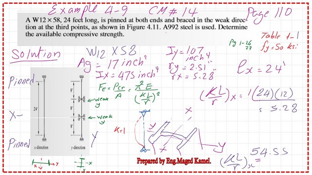
We have two points. The purpose of this solved problem is to make k*L/r in the x-direction the main criterion for evaluating the buckling load, and it is sometimes the x-direction slenderness ratio that controls the strength by controlling the bracing in the y-direction of the column.
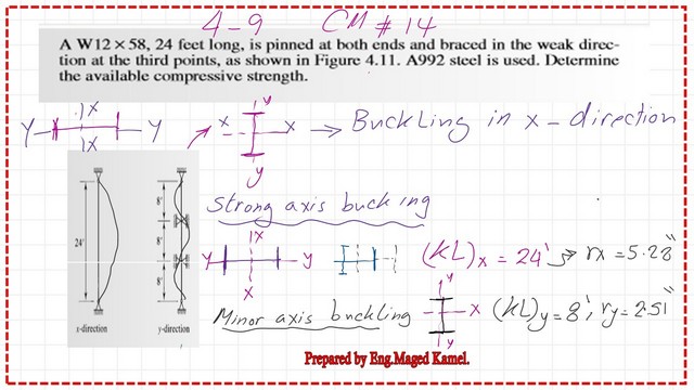
We will show the effective lengths (KL)x and (KL)y for the x- and y-directions. Please refer to the next slide for more information and the values of rx and ry for the W section.

What are the different ways to find the available compressive strength?
For the available compressive strength evaluation, we have three ways. The first one is to use the general equation after checking whether the column is long or short, since this will lead to two different equations for Fcr estimation, where Fcr is the critical stress.
The second way is to use Table 4-1, with the required (Kl)y length, which is the bigger value of Kl required from the x-direction, and Kl due to buckling in the y-direction.
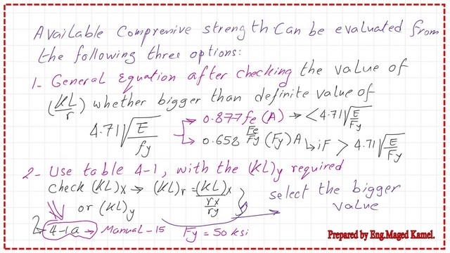
The third way is to use Table 4-22, based on CM#14, consider the bigger value of (Kl/r) of the two directions x and Y, and get the factored stress, then multiply by the area. This table is replaced by Table 4-14 in CM#15. Please refer to the next slide for more information.
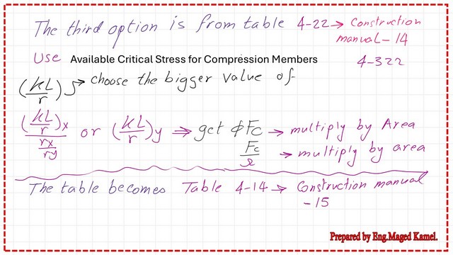
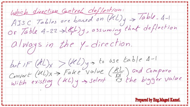
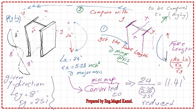
Table 4-1 is based on the assumption that the column will buckle in the Y direction. That direction will control the design, but if (Kl) is bigger than Kl at Y, we convert (Kl)x to a fake factor (Kl/rx/ry) and compare with (KL)y and then select the bigger value.
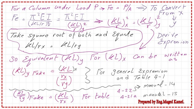
To convert from X to Y direction, consider the equation for Euler’s stress Fe =Pi^2*E/(Kl/r)x^2 equals the same stress but in the equivalent Y direction, Fe value =Pi^2*E/(Kl/r)y^2. Take the square root of the two sides, and then we can find that KL/rx=Kl/ry. The equivalent Kl at y for x- is equal to Kl/rx/ry.
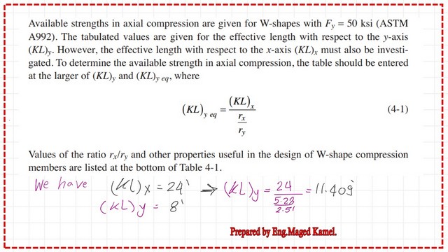
The next slide image shows the expression for (KL)y eq =Kl/rx/ry. fo our example Kl at x- direction equals 24 ft while Kl at Y=8 feet the Kl equivalent in Y from the x- direction =24/(5.28/2.51), where rx=5.28 inches and ry=2.51 inches. Then the design is controlled by the x-direction.
This is a mini-map for how to convert the buckling (KL)x about the major axis to a fake value (Kl)y, used to compare with the original (KL)y about the minor axis to decide what is the controlling factor for buckling.
The next slide image shows the values of (Kl/rx) and (Kl/ry), and that the (KL/r)x is the bigger value.
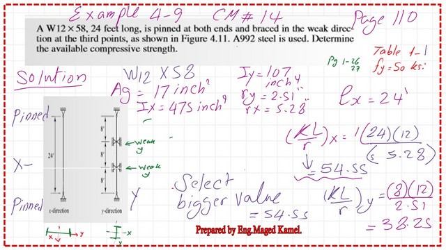
The maximum value of (Kl/r)x, which is equal to 54.55, will be compared to the limiting value of 4.71*sqrt(E/fy).
The limiting value for Fy equals 50 ksi, and the modulus of Elasticity equals 29000 ksi, which can be found to be equal to 113.43.
Our column is not in the elastic region. Hence, the critical stress Fcr is to be estimated from the relation Fcr=0.658^(Fy/Fe)*Fy. To calculate the value of Fcr, we need to assess Euler’s stress based on the buckling in the x-direction. The Euler stress is found to be equal to 96.19 ksi, as shown in the next slide image.
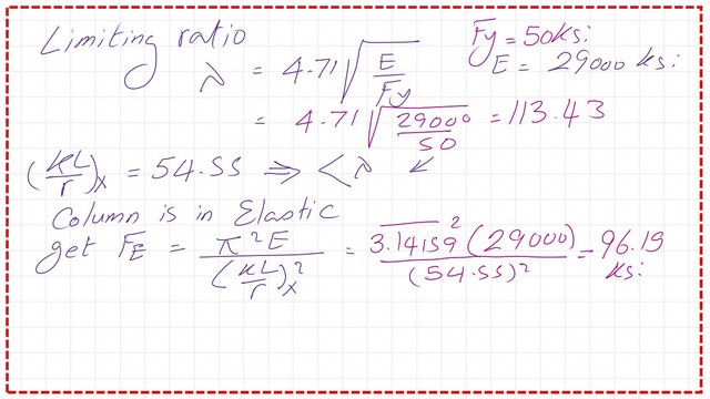
LRFD and ASD values for Critical stress for solved problem 4-9-General equation.
Once we have estimated the Euler stress, we will proceed to calculate the critical stress value, plug in all the data, and get the value of Fcr=40.22 KSi.
The LRFD value of nominal compressive stress can be estimated by multiplying phi*Fcr * area. The area is 17.00 inch2. The Phi value is 0.90. We can get the value of 615.40 kips for the LRFD design.
The ASD value of nominal compressive stress can be estimated by multiplying (1/omega)*Fcr * area. The area is 17.00 inch2. The (1/omega) value is (1/1.67). We can get the value of 410 kips for the ASD design. The factored LRFD & ASDF values for Fcr can be computed from the general equation; these values are shown in the next image.
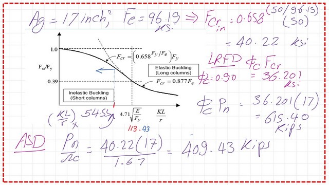
LRFD and ASD values for Critical stress for solved problem 4-9-Use Table 4-1.
We can use Table 4-1, from the construction manual -14, and specification AISC 360-10. The table will give the value of the available strength for both LRFD and ASD designs. The controlling parameter is based on the (Kl) in the x-direction=11.41 feet—the value of phi*Pn=615.18 kips for the LRFD design.
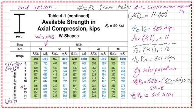
For the ASD design, the value of Pn/Ω =410 kips by using interpolation, please refer to the following slide image.
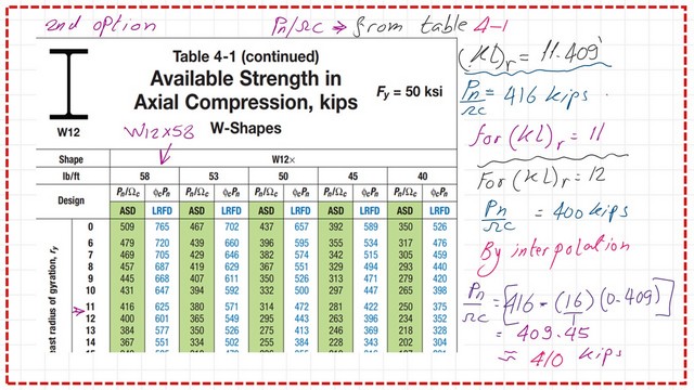
LRFD and ASD values for Critical stress for solved problem 4-9-Table 4-22.
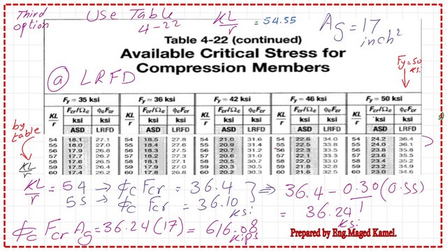
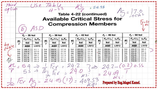
We can use Table 4-22, from the construction manual -14, and specification AISC 360-10. The table will give the value of the critical stress for both LRFD and ASD designs. The controlling parameter is based on the (Kl/r) in the y-direction.
We have estimated the controlling value of Kl/r as equal to 54.44. The factored LRFD value for Fcr can be computed from Table 4-22, phi*Fcr=36.24 ksi. We will multiply by gross area, phi*Pn=616.08 kips
The factored ASD value for Fcr can be computed from Table 4-22, (1/Ω )*Fcr=24.09 ksi. We will multiply by gross area, (1/Ω )*Pn=409.53 kips.
Thanks a lot, and I hope you will like the content of this post.
This is the next post, the Alignment chart for columns.
This is a link to an important resource, Concentrically Loaded Compression Members.