
Last Updated on May 17, 2026 by Maged kamel
How to compute Critical Stress-Table 4-22& Table 4-1?-CM#14.
On the next slide, we will find brief content for post 4: compression. What are the different Design tables for compression members to determine available strength, based on CM#14 and CM#15? We have solved the problem of estimating nominal strength using Tables 4-1 and 4-22.

How do we use Table 4-1?
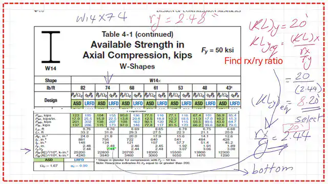
The first table used for available strength is Table 4-1, based on CM#14. But Table 4-1 requires using the larger Y (Kl) equivalent for the x-direction and the (KL)y about the Y axis.
The equivalent (Kl)y from the x-axis is equal to (Kl/rx)*ry, where rx is the radius of gyration about the X-axis and ry is the radius of Gyration about the Y-axis. The following slide image explains the difference between (Kl) yeq and (Kl)Y. This table determines available strength as factored into the Nominal load.

But there is a change in CM#15-Aisc-360-16 to the table in the Lc expression, where Lc replaces Kl. For instance, Lcy is used instead of (Kl)y, and the table is for W sections with a yield stress of Fy = 50 ksi.

Our subject as of today will be how to estimate critical stress -Table 4-22. The controlling factor that distinguishes short columns from long columns is the criterion Kl/r.
Table 4-22 gives the available critical stress for yield stresses Fy from 35 ksi to 50 ksi. The table assumes that the governing (KL/r) is in the y-direction, as the larger value compared with (KL/r)x in the x-direction.
We evaluate the maximum kL/r value that yields the minimum compressive strength, Fcr. Then we multiply by the area for the factored LRFD or ASD values.

There is no Table 4-22 in CM#15; its replacement is Table 4-14.

The same problem solved in the previous post, problem 4-2, included W14x74 of A992 steel, a height of 20 feet, and a column hinged at both ends, with the design compressive strength computed per LRFD and ASD.
The radius of Gyration about the X-direction equals 6.04 inches, while the radius of gyration in the Y direction is 2.48 inches. The values Kl/rx = 39.74 and Kl/ry = 96.77 indicate that buckling in the y-direction controls the design.

It is required to find the KL in the y-direction.

We need to select the larger of K*Ly values. We need to convert k*lcx into k*lyeq by dividing K*lcx by the rx/ry ratio, which we can find at the bottom of Table 4-1. We have two values for kl with respect to Y: 8.20 ft and 20 ft. We select the maximum value, which is 20 Ft. We will use it later for part B.
How to compute critical stress-Table 4-22?-LRFD design.
We are going to use Table 4-22, with yield stress Fy = 50 ksi, first for LRFD. For k*L/r = 96.77, it is between 96 and 97. For LRFD, at 96, the value is 22.9. Since 97 has a value of 22.6, our value will be < 22.9.

The next slide image shows how we use linear interpolation to find the value for φ*Fcr of 22.67 ksi, we will multiply by the area to get the load for the LRFD there and estimated as =22.9 minus the difference between (22.9-22.6) * 0.77/ 1, which will give the value for φ*Fcr of 22.90 ksi, we will multiply by the area to get the load for the LRFD =494.18 kips.

How to compute critical stress-Table 4-22?-ASD design.
This is Table 4-22, we are checking the critical stress based on the ASD design. For ASD, for K*L/r= 96, (1/Ω)*Fcr= 15.30 ksi, while for K*L/r= 97, (1/Ω)*Fcr= 15.0 ksi. So (1/Ω)*Fcr for 96.77 is <15.30 ksi and is estimated as (15.30 – (15.30-15.00) * (0.30/1)) = 15.07 ksi. We will multiply by the gross area A to get the ASD load: (1/Ω)*Pcr = 328.50 kips.

How to compute critical stress-Table 4-1?-LRFD and ASD design.
To use table 4-1, we need to find the equivalent (Kl)y=Kl*ry/rx=20*12*2.48/6.04=8.21 feet. We compare with (KL), the effective length in the y-direction, which is equal to 20 feet. Since Kl at y is greater than (KL)y, we use the larger value for Table 4-1. Please refer to the following slide image for more information.

How to compute critical stress-Table 4-1?-LRFD and ASD design.
For Fy=50 ksi, for W14x74, the φ*Pn=495 kips, while for the ASD design (1/Ω)*Pcr =329 kips. These figures are very close to the values obtained from Table 4-22.

Thanks a lot, I hope the information is useful.
The PDF for this post can be viewed or downloaded from the following link.
If you wish to review post 3 for the Column Compressive strength by the general provision
This is the next post, post 5, “A Solved Problem 4-9,” on available compressive strength.
For a good A Beginner’s Guide to the Steel Construction Manual, 14th ed. Chapter 7 – Concentrically Loaded Compression Members.
For a good A Beginner’s Guide to the Steel Construction Manual, 15th ed. Chapter 7 – Concentrically Loaded Compression Members.
For a good A Beginner’s Guide to the Steel Construction Manual, 16th ed. Chapter 7 – Concentrically Loaded Compression Members