Last Updated on October 10, 2024 by Maged kamel
Introduction to design of continuous beam, solved problem 4-15.
Detailed illustration of the design of a continuous beam based on LRFD.
The following steps will be followed to Design a continuous beam.
1-Estimate The Ultimate load for which we have the maximum value of 1.20 Wd+1.60WL or 1.40 Wd for the given two-span continuous beam.
1-For Wult=1.20*1+1.60*3=1.20+4.80=6.00 kips/ ft, the other possibility of 1.40Wd=1.40*1=1.30 kips/ ft. The maximum value for Wult selected will be Wult=6.00 kips/ft.
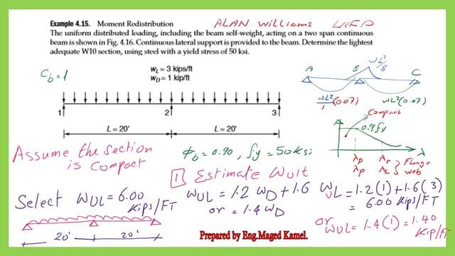
2-Estimate the maximum M+ve and M-ve values. From statistics, we know that M-ve = Wult*L2/8, where L is the span length.
For M+ve, the value is 0.07*w*L2/, and the ultimate positive and negative moments are M+ve = wul*L2*0.07 for the LRFD design.
3-Then M-ve=6*20^2/8=300 ft.kips. As for M+ve=0.07*6*20^2=168 ft.kips.
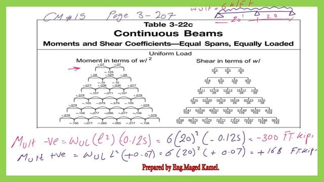
4-Since the given beam is a continuous beam, perform a reduction of negative moment Mult-ve=0.90*Mult, this value will be the final value of Mult -ve, then add the average of this value to Mult +ve, to get the final Mult+ve.
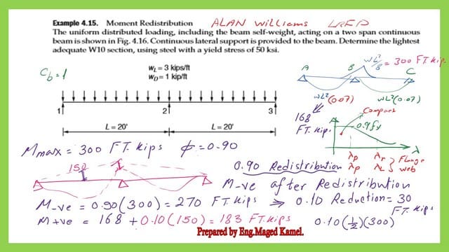
The M-ve for design=0.90*300=270.0 Ft-kips is based on the LRFD design. As for M+ve final=168+0.100.5*300=(168+15)=183.0 ft.kips
5-Select the maximum value of Mult+ve and the Mult -ve. Consider this maximum for the solved problem 4-15. Mult=0.90*Zx*fy; hence, the value of Zx can be estimated as Zx=Mult/(0.90*fy). We have Fy=50.0 KSI and Mult=270.0 ft. kips.
The value of Zx is 270*12/(0.90*50)=72.0 inch3. 6-From Table 3-2, where the W sections are arranged and sorted based on Zx, based on the author’s requirements of selecting the lightest W10 section.
We can select the w10x60, which will give the plastic section modulus Zx value as =74.60 inch3>72.0 inch3 as required by the estimation.

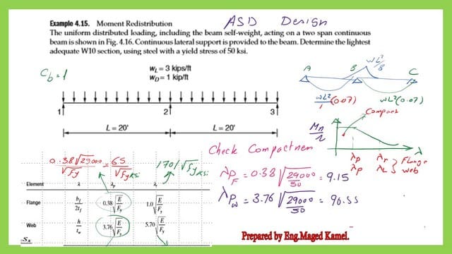
7—Check the compactness of the selected section, as shown in the next slide image. If we want to calculate it manually, check whether the section is compact by estimating λf and λweb is less than the criteria given by the AISC specifications.

We need to go to Table 1-1 to find the data for bf, d, he, and tw, or we can get the compactness ratios directly from the table.

8-Estimate the final (φ)Mn, when having φ=0.90, while Mn=FyZx=5074.60=310.83 ft.kips, then finally/12=(φ)Mn=(0.90)*310.83=279.75. 18ft. kips approximated to 280.0 ft. kips.

We can use Table 3-2 to verify our previous calculations for the LRFD design.
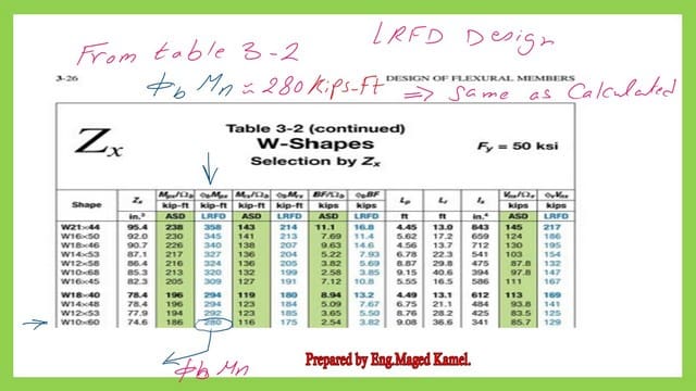
Illustration for the design of a continuous steel beam based on ASD.
1-Estimate The Total load for which we have the maximum value of Wd+WL for the given two-span continuous beam.
A-For the total load Wt=1+3=4.0 kips/ ft.

2-Estimate the maximum M+ve and M-ve values. We have from statistics that M-ve = Wt*L2/8, where L is the span length. For M+ve, the value is 0.07*wt*L2/, and the ultimate positive and negative moments are M+ve = wt*L2*0.07 for the ASD design.
3-Then M-ve=4*20^2/8=200 ft.kips. As for M+ve=0.07*4*20^2=112 ft.kips.

4-Since the given beam is continuous, perform a reduction of negative moment M-ve=0.90*Mt. This value will be the final value of Mt -ve. Then, add the average of this value to Mt +ve to get the final Mt+ve.
The M-ve for design=0.90200=180.0 Ft-kips based on the ASD design. As for M+ve final=112+0.100.5*200=(112+10=122.0 ft.kips.
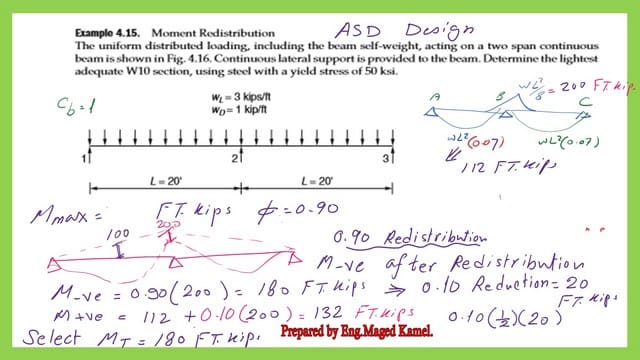
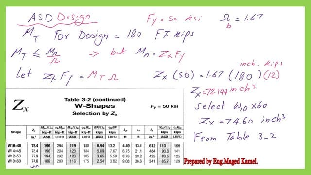
5-Select the maximum value of Mt+ve and the Mt -ve, and consider this maximum for the solved problem 4-15, Mt=(1/1.67)*Zx*fy. Hence the value of Zx can be estimated as Zx=1.67 Mt/(Fy), we have Fy=50.0 KSI and Mt=200.0 ft. kips, then Zx value=(1.67*200)*12/(50)=72.0 inch3.
6-From table 3-2, where the W sections are arranged and sorted based on Zx, we can select the lightest W10 section based on the author’s requirement of selecting the W10x60, which will give the Zx value as =74.60 inch3>72.0 inch3 as required by the estimation.
Check the compactness of the selected W section-ASD design.
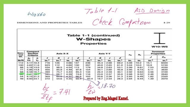
8-Estimate the final (1/Ω)*Mn, when having Ω=1.67, while Mn=Fy*Zx=50*74.60=310.83 ft.kips, then finally/12=(1/Ω)*Mn=(1/1.67)*310.83=186.18 ft.kips. This is the last step in the design of a continuous steel beam based on the ASD design.

We can get the same result for the factored moment from tables 3-2 for section W10 x 60 Based on the ASD. Please refer to the next slide image.

Thanks a lot; I hope the post is useful.
This is the next post, Collapse Load for A Simply Supported Beam.
A Beginner’s Guide to Structural Engineering.