Last Updated on March 7, 2026 by Maged kamel
Part 1/4 of the solved Problem 9-9-6, How to Find Service LL?
Solved problem 9-9-6 from Prof. Salmon’s Book.
This is the content of the lecture and the sequence of items for calculations of the solved problem 9-9-6.

The following slide includes a brief of what we will check in this post.

A solved problem 9-9-6 from Prof. Charles Salmon’s book. A solved problem 9.9.6 from Prof. Charles Salmon’s book.
Please look at the small sketch, given the welded I-beam section used as a 45-ft beam laterally supported at the one-third point.
The I-beam section consists of three plates welded together; the Upper plate, representing the flange, is a plate with the dimensions of (16″x5/8″).
The web part is a plate with a dimension of (26″x5/16″).
The lower flange plate is similar to the upper plate (16″ x5/8″). The yield stress Fy is given as 65 ksi, and E, the modulus of elasticity, is 29×10^6 psi, or sometimes written as 29000 ksi. Loadings are shown in the next image; bracings are located at the third point.

We want to check the compactness of the flange and web and determine which F equation to use. Please refer to the details of the different F types for doubly symmetric sections based on Chapter F of the specification.


What is the local buckling λ parameter for the flange?
We cannot take λr=1*sqrt(E/Fy) as case no.1 for flanges of Rolled I-shaped sections. We will use case No. .11 to get the values for λp and λr for the flange of the Built-up section. Please refer to case Number 15 of Table B4.1b for the web parameters.

This is a clear copy of Case 11 for the Built-up section, where the Flange λp has the same value as in the first case, λp = 0.38*sqrt (E/Fy), while λr = 0.95*sqrt (Kc*E/Fy), with a new factor Kc.

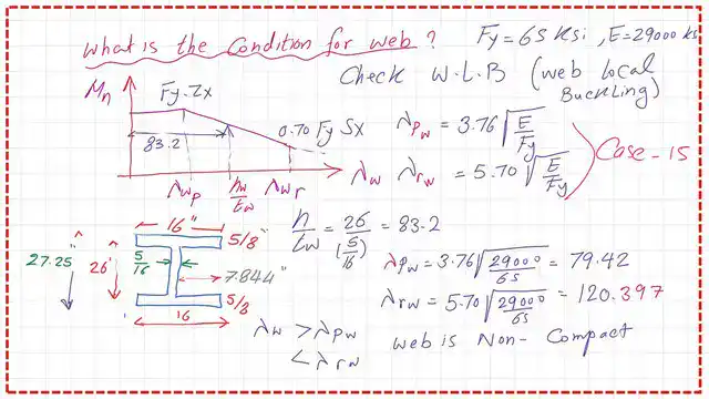
This is a clear copy of Case 15 for the Built-up section, where, for the web, λp=3.76*sqrt(E/Fy), while λr=5.70*sqrt(Kc*E/Fy).

This is the calculation for the coefficient of the Kc value. This is the Built-up section, 16″ x5/8″, with an inner height of 26″ and a thickness of 5/16″. kc factor=4/sqrt(h/tw), h/tw=26/(5/16)=83.20,then kc=4/sqrt(83.20)=0.4385. kc should be >0.35 but < 0.763; in our case, we have 0.4385.

Find λp and λr for the Flange Local buckling parameters.
The Built-Up section is given, and we have λp for the flange equal to 0.38*sqrt(E/Fy). Since E = 29000 psi and Fy=65 ksi, the value of λrF will equal 8.026.
For the flange, we have λr = 0.95*sqrt(Kc*E/Fy).
Since E = 29000 psi and Fy=65 ksi. t value of λrF will be equal to 0.950.95*sqrt(Kc*E/Fl)= 0.95 *sqrt(0.44*29000/0.7*65)=15.90.
Bf/2Tf =16/2*5/8=12.80. The Value of Bf/2tf is bigger than λp but less than λr. Thus, the flange is Non-compact. The Mn will be less than Fy*Zx and bigger than 0.75Fy*Sx.

Estimation of Zx for the section of the solved problem 9-9-6.
What is the value of Mp and also the value of 0.70*Fy*Sx? We must estimate the Zx and Sx values for the solved problem 9-9-6. What is the formula for Zx?
This is the total section due to bending. A compression force will act on the CG of half of the section. The neutral axis N-A is in the middle, but there are two forces, C1 and C2.
Force C2 acts on the web side until the N-A. C1 and C2 have equivalent forces to T1 and T2. These forces develop the plastic moment Mp.
Zx=At*(2*y bar)/2, 2*y-bar is the distance between the Cg of the Compression force and the Tension force.
We call it Yct, or the distance between compression and tension forces.
The plastic section modulus Zx=At*Y bar. The formula is widely used for irregular shapes.
AT/2 is the area of the top flange and half the area of the web. AT/2=A1+A2.
AT/2=(16*5/8)+(13*5/16))=10+4.06=14.06 inch2. Y1 is the distance from the CG of the first area A1 to the N A.
Y1=13+0.50*(5/8)=13+(5/16)=13.3125″.
For A2, the height=13″ and thickness=5/16, then Y2=13/2″. AT/2*Y bar=A1*y1+A2*y2, then ybar=10*13.3125+4.06*6.50)/14.062. ybar=11.344″.
Zx=At*y bar=2*(14.06)*11.344=319.06 inch3. For the upper point of the graph, Mp=Fy*Zx.

Find λp and λr for the Flange Local buckling parameters.
For the web the h is=26′, tw=5/16″, λw=26/(5/16)=83.20. λwp=3.76*sqrt(E/fy)= 3.76*sqrt(29000/65)=79.46.
λw is >λwp.
Let us check the value of λw-r= 5.7*sqrt(E/Fy)=5.7*sqrt(29000/65)=120.40, λw is >λwp.
But <λwr, the section is also non-compact for the web for the local buckling.
The section is non-compact for both the flange and the web due to λ values >λp. but <λr Mn will be < Mp.
Mn is not the product of Fy*ZX. This is the end of part 1 for solving problem 9-9-6.
The PDF used for this post can be viewed or downloaded from the following document.
For the next post, part 2/4 of the solved problem 9-9-6, how do we find LL for a slender section?
Here is the link to Chapter 8 – Bending Members, section, A Beginner’s Guide to the Steel Construction Manual, 14th ed.
Here is the link to Chapter 8 – Bending Members, section, A Beginner’s Guide to the Steel Construction Manual, 15th ed.
Here is the link to Chapter 8 – Bending Members, section, A Beginner’s Guide to the Steel Construction Manual, 16th ed.