Last Updated on February 25, 2026 by Maged kamel
Solved Problem 10-2: How do we use Table 3-2 For Shear Value?
A solved problem 10-2, check shear adequacy for the selected section.
This post has two parts. The first part discusses solved problem 10-2, while the second part discusses the nominal shear for steel beams based on CM#15 and specification 2016.
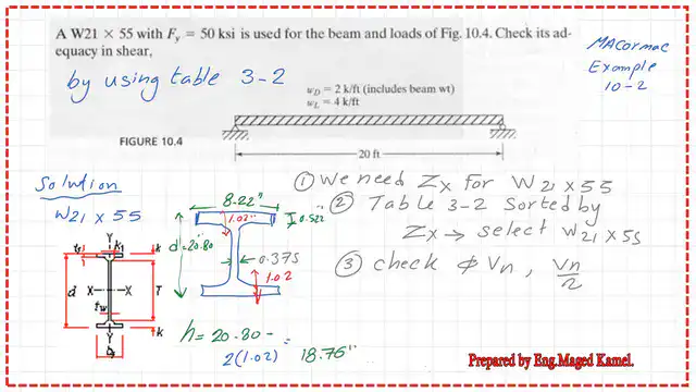
This is a solved problem 10-2 from Prof. McCormack’s book. There is a beam with a W21x55 section for which the yield stress Fy equals 50 ksi. Check the adequacy of this beam to shear using Table 3-2.
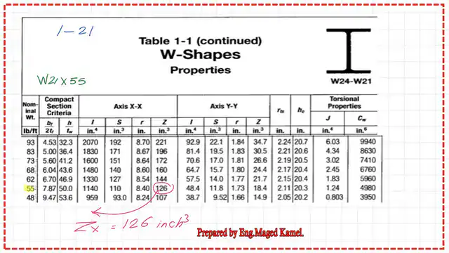
Table 1-1 shows all the relevant data for W21x55. A section of W21x55 is drawn, as shown in the small sketch on the left side.
From Table 1-1, we obtain the plastic section modulus Zx for the W section W 21×55, which is 126.0 in³.
From Table 3-2, where the plastic section modulus Zx is sorted. In the W section W 21 x55, the LRFD value for the nominal shear can be obtained from the final column. The value equals 234.0 kips, which matches the same figure from the previous post.

The ASD value for the allowable Nominal shear strength is in Table 3-2. We can determine the ASD shear strength, which is 156.0 kips. The attached image shows the figures for both the LRFD and ASD.
AISC specification provision for the design of Members for shear-CM#15.
Chapter G is the designated chapter for the design of members for shear.
Clause G-1 is for the general provisions. Item G2 deals with stiffened and unstiffened steel sections, including W, M, Hp, and S. The other sections not included in G2 are shown in G3, G4, G5, G6, G7, and G8. Please find the data in the next slide image.

The next slide shows the Nominal value for shear.

There is a new term, Cv1. Unlike CM#14, the coefficient of shear was Cv. There is a user note stating that for all current A6 steel, W, S, and Hp sections, the h/tw ratio must meet the requirement of 2.24*sqrt (E/Fy), except for W44x230. W40x149 and some other sections do not confirm. We will check the section W40x149’s h/tw ratio. Please check the next slide.

The Kv coefficient equals 5.34 for the unstiffened web. For a stiffened web, Kv equals 5 + 5/(a/h)^2. The term a is the precise distance between the transverse stiffeners. While h is the clear distance between flanges.
There is a user note for sections. A6, W, S, M, and Hp confirm the requirement of 1.10*/sqrt(KC*E/Fy) except M12.50×12.4. M12.5×11.60, M12x11.80, and some other sections do not confirm. We will check the section M12.5×12.40’s h/tw ratio. Please check the next slide.

Check section W40x149 for shear and estimate the Nominal shear strength.
For the W40x149 section, there is a list of data, area, flange width, flange thickness, web thickness, and h/tw. The ratio h/tw equals 54.30; when we compare with 2.24*sqrt*(E/Fy), which equals 53.94 for Fy=50 ksi, we find that h/tw for W40x149 is bigger than 53.94 but smaller than the 1.10*sqrt(Kv*E/FY), which equals 61.22 for Fy=50 ksi. Cv1 value equals 1.

The factored nominal shear for section W40x149.
The next slide provides a detailed estimate of the shear strength for the LRFD and ASD designs.PHi*Vn equals almost 650 kips, and the Vn/lambda=432 kips; please refer to the next slide for more details.

We use Table 3-2 to check the estimated factored shear load; we will find a match between the previously estimated values and those from Table 3-2, as we can see from the next slide.

Check section M12.5×12.40 for shear and estimate the Nominal shear strength.
To check the M12.50×12.4 section, which is included in the user note, we find the h/tw ratio from tables 1-2 for M sections; it equals 74.80. The depth is 12.50″, and the tw is 0.155″. The h/tw is greater than 1.1*sqrt (Kc*E/Fy), which equals 31.22 for Fy=50 ksi; please refer to the next slide for more details.

I use the graph between Vn and the ratio h/tw for M12.5×12.4, represented by point 3 on the x-axis. To find Vn, it equals Cv1* (0.6*)* Aw. We estimate Cv1 to be 0.818, which is less than 1. Aw=d*tw, and Fy equals 50 ksi. Vn=47.55 kips.

We have reached the end of our post, which is the factor shear stresses for M12.50×12.4. Please refer to the next slide image for more details. Phi is equal to 0.90, and omega is equal to 1.67. Thanks a lot.

A good resource for the shear stress limit state. Section 8.3.2-Shear Strength Limit State-15 ths edition.
A good resource for the shear stress limit state. Section 8.3.2-Shear Strength Limit State-16 ths edition.
This is a link to a previously solved problem that was checked using the AISC provision in this post.
For a solved problem for the S steel shape for shear, please refer to post-41s-Nominal shear strength for S41x121.
This is post 24: Deflection of steel beams.