Last Updated on June 23, 2024 by Maged kamel
An easy approach to Compact and non-compact sections.
What is a compact section?
A compact section can develop a plastic hinge before local flange or web buckling, providing adequate lateral bracing. The member will fail in overall yielding before failing in local flange or web buckling.
The Noncompact sections do not satisfy the limiting width-thickness ratios for compression elements.
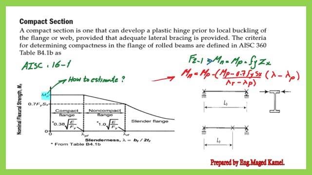
Table B4.1B expresses the relation between lambda and MN in three zones. The graph shows that the first zone is compact, the second zone is non-compact, and the last zone is a slender flange.
If we draw the graph representing the relation between the lambda λ and Plastic moment MP, consider λf=(bf/2tf) for flange, while for web λw=hw/tw. We start with the case of a flange, which is more critical since the lambda λ value for the web is nearly safe for most of the steel sections.
The vertical axis represents the nominal moment Mn. The design is based on the Plastic moment MP. The graph starts as a straight line from λ=0 to λ=λp.
In the case of the flange. The area under the straight line from λ=0, λp, is called a compact flange.
This can be achieved by placing concrete over the steel section’s flange. The flange is kept in place and braced through studs, and the buckling length will be 0. In that case, the steel section will be considered a compact section.
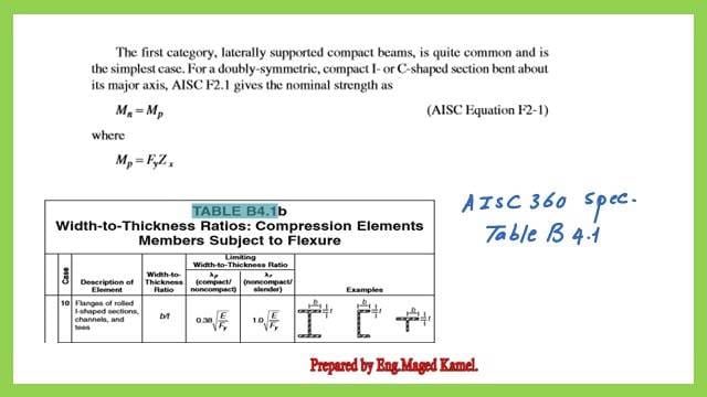
The criteria for determining the compactness of rolled beams are defined in AISC 360 Table 4.1b; please refer to the second slide.
The table expresses the relation between lambda and MN in three zones, as shown in the graph: the first zone is compact, the second is non-compact, and the last is a slender flange.

What are the different zones for flanges?
The first zone is compact, in the case of a flange, the flange is prevented from moving laterally by providing a stud and the covering slab has a range from λf=0 to λf=λp.
The second zone for the lambda of the flange, lambda, is called λrf. At that time, the flange starts to have lateral buckling. The flange section is considered a non-compact flange.
The third zone represents a slender flange. The slender flange behaves similarly to a column that has a lateral buckling.
The following expression for lambda value for the flange, where Fy is the yield strength, and E is the modulus of elasticity.
While for the value of λf=λFr=1.0*sqrt(E/Fy).
The first category, laterally supported compact beam, is quite common. For a doubly symmetric, Compact I beam, or C-shaped section bent on the major axis, AISC F2.1 gives the nominal strength as Mn=MP, where MP=Fy*ZX and Zx is the plastic section modulus.
This is part of table B4.1b, quoted from the AISC 360 spec. For item 10, for flanges of rolled I-shaped section, C channel, and Tees, lambda =b/t, where b is the width of the C channel, while for I beam and T section, b is considered half the total width. Please refer to Table B4.1B, which is included in the next slide image.

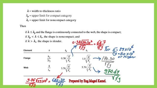
The next slide shows the different values of λf equal to (bf/2tf) when λf=λp, which is the plastic lambda value. The value equals 0.38*sqrt(E/Fy) and can be set to 64.7/Sqr(Fy) for any value of Fy, while E=29000ksi. When λf=λr, its value equals 1.00*sqrt (E/Fy) and can be set equal to 170.30/sqrt(Fy).
The web has three zones but different values for lambda, as shown in the next slide. The approximate values for the yield stress Fy value of 50 ksi are shown. For more details about the content of table B4.1b, please refer to post 7-7- A guide to Local buckling parameters for steel beams.

Here is a link for an excellent external reference for steel beams.-A Beginner’s Guide to Structural Engineering.
This is the next post- 3-Introduction to Plastic Theory.