Last Updated on July 17, 2025 by Maged kamel
Analysis of portal frame-fixed supports at base.
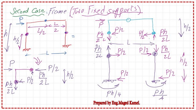
The Portal frame is analyzed into one frame and two cantilevers.
The second case is for the portal Frame when it has a fixed support at the base, the inflection points are located at the mid-height of the columns in addition to the hinge at the midpoint of the girder. This solution is an approximate solution to facilitate the design.
The upper part above the hinge is represented separately, with three hinges. This part is the same as the one we have already solved, which is a portal frame hinged at the supports. The only difference lies in the fact that the height in this case is h/2.
While the forces at the joint derived earlier were P*h/L at the support on the left and the right, the same value but in opposite directions.
At the left joint, P*h/L acts downwards, while at the right support, there acts upwards, so the joint reaction =P* height/L.
Estimation of the portal frame reactions.
The height from the upper floor to the lower hinge is equal to h/2.
To estimate the left joint Reaction it will be found that is equal to P*h/(2*L) acting downwards, and at the right support, Reaction=P*h/(2*l) acting upwards due to joint balance, there will be P*h/(2*L) force acting downwards for the lower part at the hinge at the left column at height=h/2.
How to draw a moment diagram of a portal frame with fixed supports at the base?
We have a horizontal force =P/2 acting to the right and a vertical force=P*h/L acting upwards. Regarding the bending moment, the moment due to a couple will rotate in this manner. Then, the support moment to create stability will act in this direction, anti-clockwise. The moment will be (P/2)*(h/2)=P*h/4.
Let us have a look at the right portion of the joint. We have P/2 at the right hinge acting from right to left, as opposed to a force P/2 from left to right. We have a vertical force, Ph/2L, acting upwards, and an equal and opposite force, Ph/2L, acting downwards.

The couple at the right side =(P/2*h/2), opposed by the moment at the support.
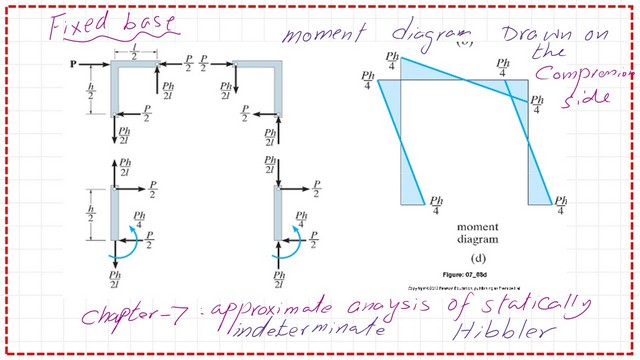
The moment at the left support, Ph/4, acting anti-clockwise, is also the exact moment value at the right support of the portal frame, with fixed supports at the base.
For the Moment values due to superposition, we have a negative moment, zero at the mid-column height, then reversed at joint C The slope is =0, then the slope starts to increase as the moment increases. Let us examine the bending moment diagram and the other forces at joints. However, the moment is drawn differently than what we have drawn.

The moment value is P*h/4, and the reaction = P*h/2L as a vertical reaction, which we have evaluated. When drawing the moment, we place it at the tail of the arrow, yielding the same values.
I have included a practice problem as an application for the portal frame with a fixed base.


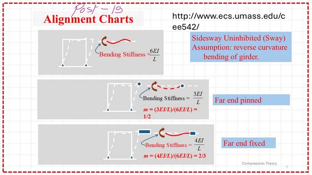
Introduction to m value for alignment chart for the unbraced frame.
The new subject is the modified factor m value. From this link, UMass, there is valuable information for structural steel design, from which I have copied these shapes. I have put the link to the AISC code teaching aids. Please download the data and check the compression members
. There is a modification to the alignment chart that should be applied to the three cases shown in the next slide image.

We will continue our discussion about m values for the side-sway uninhibited in the next post.
The Core Teaching Aids for Structural Steel Design Courses provide valuable data that can be downloaded from the AISC link.
This is a link to a handy external link Concentrically Loaded Compression Members.
This is the next post, a modification to the alignment chart.