
Last Updated on October 5, 2026 by Maged kamel
Mohr’s Circle of inertia-third case-part 2.
In this Post, Mohr’s Circle of inertia-third case-part 2, we will be interested in showing the steps to draw Mohr’s Circle of Inertia in the third case, where Ix is bigger than Iy, and Ixy is negative. The IMAX Value equals (Ix + Iy)/2 plus R, the Circle’s radius.
For minimum Inertia, Imin equals (Ix + Iy)/2 minus R, where R is the Circle’s radius. The Value of- 2θp1, which is more than 90 degrees, equals 180 – 2θp2. In the normal view, the U axis is in the first quarter, while the V axis is in the fourth quarter, as shown in the next slide image.

The steps used to draw Mohr’s Circle of inertia-third case-part 2.
To draw Mohr’s Circle of Inertia, third case-part 2, first draw the two orthogonal axes. The first axis represents the Moment of Inertia values, Ix, Iy, and Imax, and the minimum values, while the second axis represents the values of the Product of Inertia, Ixy.
The coordinates of Point A are (Ix, -Ixy); the negative Value of -Ixy comes from the case data. Point B has coordinates (Iy,+Ixy), and the Value of Ixy is the negative Value identical to the Ixy of Point A. Locate points A and B with their respective values of Ix and Iy, as shown in the next slide image.
Join Points A and B and find the Midpoint of line AB. This Point is the center of the Circle, which is Point O. The radius Value is sqrt( (Ix-Iy/2)^2+Ixy^2). Start at Point O and draw the Circle with the just-estimated radius. The Circle intersects the line at two points, C and E.
Point E is the maximum Value of Ix, and it equals (Ix + Iy)/2 + R. Point C is the minimum Value of Ix, and it equals (Ix+Iy)/2)-R.
We can find that line OA represents the x-axis in Mohr’s Circle, while axis OB is the Y-axis in Mohr’s Circle.

Need for two mirror points A’ and B’ in Mohr’s Circle of inertia-third case-3 part 2.
In Mohr’s Circle of inertia-third case-part 2, we need two mirror points. Set Point A’, the mirror of Point A with coordinates (Ix, +Ixy), which gives the direction of the maximum Moment axis U. This Point A’A’ lets rotate the x-axis line OOA clockwise by 2θp1. The x-axis will be horizontal; the U line will also have a new direction represented by line OA’.
Point B’ is the mirror of Point B and has coordinates(Iy,-Ixy) and is used to indicate the direction of the V-axis, which is the direction of the minimum Moment of Inertia axis.
Angle 2θp1 is the angle between the X-axis and the Major axis U, which is the angle enclosed between OA and Line OE. Point E is the Point of maximum Inertia.
Angle 2θp2 is the angle between the x-axis and the minor axis V, which is the angle enclosed between OA and Line OC. Point C is the Point of the minimum Value of Inertia.

The direction of U and V axes in normal view using Mohr’s Circle of inertia-third case-part 2.
Join points OA’ to get the U-direction. Join the two points O and B’ to get the V-direction for the normal view, the view from which the x and y axes are orthogonal in the normal view. The directions of both the U and V axes are shown in the next slide image.
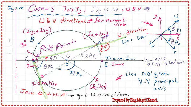
For the orientation of two axes, Ixy and Ix, with the x-axis horizontal, Point E is where Ix’ = Ix at 2θ = zero and Ix’y’ =- Ixy,xy since OE is horizontal, while Point B’ has Ix’ = Iy and Ix’y’ = +Ixy.
This drawing satisfies the requirements of Case 3: Ix is larger than Iy, and Ixy is negative. An angle of (φp2) rotates the V axis clockwise from axis X, while the U axis rotates by an angle of (2φp1) anticlockwise from axis X.

You can refer to the first part for more information
You can view or download the PDF data for this Post and the previous Post.
In the next Post, we will solve a Problem that covers the third case of Mohr’s Circle of Inertia.
This is Linknk to a valuable external resource—calculator for Cross-Section, Mass, Axial and Polar Area Moment of Inertia, and Section Modulus.