Last Updated on November 24, 2025 by Maged kamel
Stiffness reduction factor for inelastic columns-part 2.
In the previous post, we talked about the difference between Fcr from the Euler graph and the Fcr for inelastic columns. Please refer to this link for review.
How do we get the expression of the Stiffness reduction factor for inelastic columns?
Prof. Segui has introduced various equations to get an expression for τb, using Fcr inelastic term.
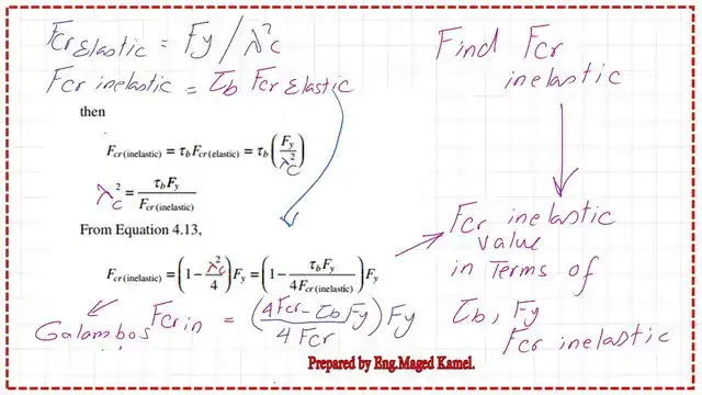
Using the λ^2=Fy/Fcrelastic based on Galambos’ second equation, then *(Fcr inel/Fcr inelastic), use the τb= Fcr in/Fcr elastic, then we get λ^2=τb*(Fy/Fcr inelastic).
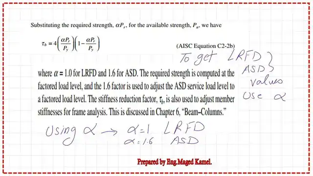
We get the final Expression τb, the stiffness reduction factor τb = 4*(Fcr/Fy)*(1-Fcr/Fy).

If we use the stress expression, in terms of loads, the stiffness reduction factor will be τb =4*(Pn/Py)*(1-Pn/Py), Pn=Fcr*Ag, Py=Fy*Ag.
The previous expression was further modified by the load, which can be expressed in both the LRFD or the ASD format; another α factor was introduced.
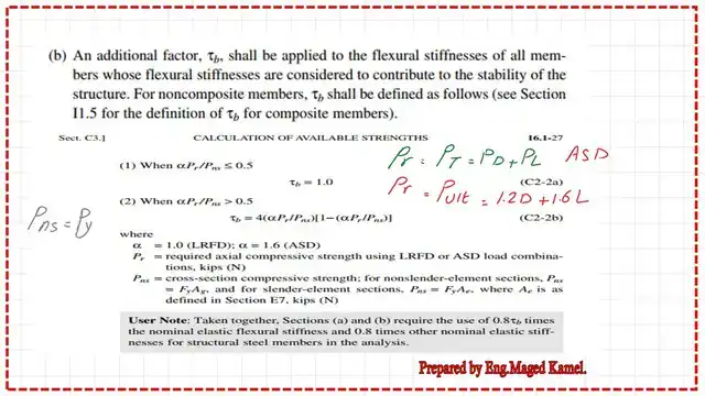
There is a new factor, termed α; In the case of the LRFD design, α = 1, and for the ASD design,
α = 1.6. This is the code provision. First, check that α*Pr/Pns <=0.50. If we use Pns, this is considered Py in all cases, with an α factor of 1 for LRFD, and Pr = Pult = 1.2 D.L + 1.60L.
In the case of ASD then Pt=Pd+PL, refer to τb equation, for the pr expression (α*Ppr)=(1*Pult)=(1*Pult), the Pns =Py, in case of ASD,(α*Ppr)=(1.60*PT).
The new slide shows various types of curves, as quoted from the UMass link, which includes a handy illustration for compression steel members. The blue curve is the Euler curve, and the dotted curve in yellow is the inelastic column curve, which has Et<E.
While the dark blue color curve is the AISC code provision for inelastic columns, the Fcr equation can be divided into two parts. In the first part, the elastic columns, where Kl/r>4.71(sqrt(E/Fy) differentiate between the elastic and inelastic columns.

The value of Fcr for elastic columns is equal to 0.877 Fe, while Fcr for inelastic columns equals 0.658 raised to λ^2, all multiplied by Fy.
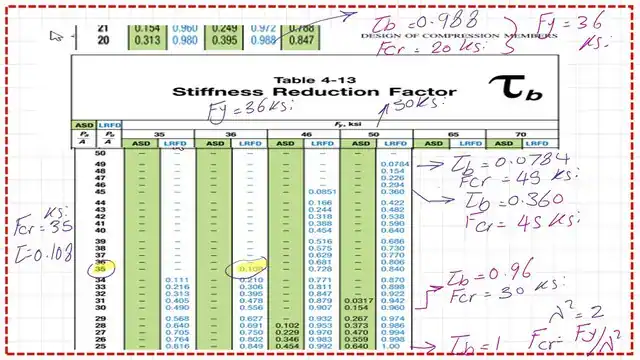
Table 4-13 for stiffness reduction factor.
This is Table 4-13, which is used to determine the value of the stiffness reduction factor for inelastic columns, τb.
The table is divided into the upper row for the different values of the yield stress Fy.
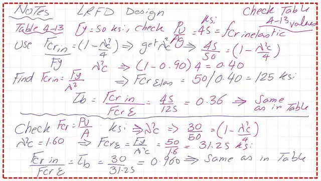
Check two values of Pu/Ag for the yield stress of Fy = 50 ksi (LRFD design).
I have prepared a check to verify the value of the inelastic stiffness reduction factor τb for Fy = 50 ksi. The first point is the value of Pu/Ag = 45 ksi; I have estimated both the elastic and inelastic critical stresses. The final τb equals 0.36, which is the same value as included in Table 4-13.
The second point is the value of Pu/Ag=30 ksi; the final τb equals 0.96, which is the same value as included in Table 4-13.
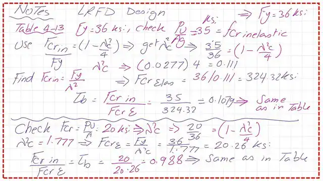
Check two values of Pu/Ag for the yield stress of Fy = 36 ksi (LRFD design).
I have prepared a check to verify the value of the inelastic stiffness reduction factor τb for Fy equal to 36 ksi. The first point is the value of Pu/Ag = 35 ksi; I have estimated both the elastic and inelastic critical stresses. The final τb equals 0.1029, which is the same value as included in Table 4-13.
The second point is the value of Pu/Ag=20 ksi; the final τb equals 0.988, which is the same value as included in Table 4-13.
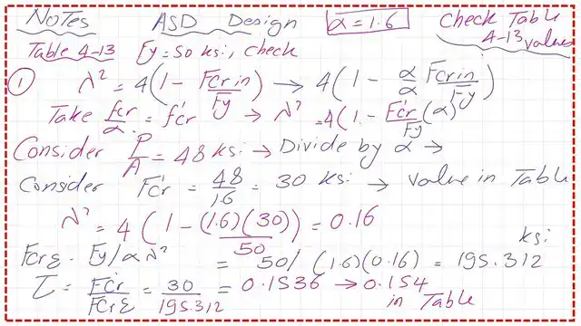
Check one value of PT/Ag for the yield stress of Fy = 50 ksi (ASD design).
For a given stress of 48 ksi, we divide by alpha, which is 1.60, and we call Fcr’, which is equal to 30 ksi. Next, we estimate lambda^2 as equal to(4-alpha*fcr’/Fy)=0.16. Next, we estimate fcr elastic=Fy/(alpha*lambda^2)=50/(1.6*0.16)=195.312 ksi.
Finally, τb equals (30/195.312)=0.154. This value matches the value given by Table 4-13.
On the other left side of the Table, Pt/Ag, as in the case of ASD, if Pt=Pd+Pl, and in the case of LRFD, we use Pult/Ag.
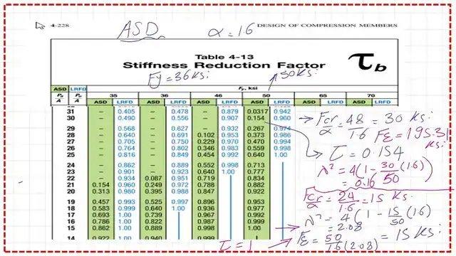
This is a slide image for table 4-13, for Fy=50 ksi, for the part of ASD design, where fcr/alpha=30 ksi, and the tau value is verified as equal to 0.154. When tau=1.00, this is at Fcr=15 ksi, the elastic stress is also equal to 15 ksi.
In the following post, we will introduce a solved problem 4-13 to estimate the stiffness reduction factor.
A handy external link is Chapter 7 – Concentrically Loaded Compression Members.
The following post will be a solved problem 4-13 for the stiffness reduction factor.