Last Updated on February 14, 2026 by Maged kamel
Problem 3-4-3 for staggered bolts-tension members.
This post reviews the solved problem 3-4-3 for staggered bolt-tension members. This problem is quoted from Prof. Segui’s handbook, 5th edition. The main aim is to investigate the different failure roots of failures and the corresponding net areas.
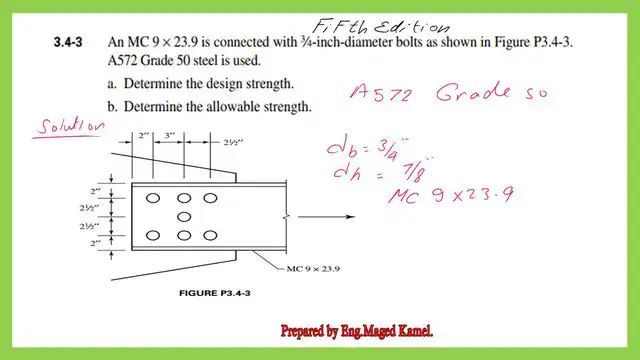
An MC9x 23.9 is connected by 3/4-inch bolts, as shown in Figure P-3.4-3. ASTM A572 steel is used. a) Determine the design strength and b) Determine the allowable strength.
Prof. Segui has considered the actual force acting on each net area and adjusted the estimated net area, which we will see in the next calculations.
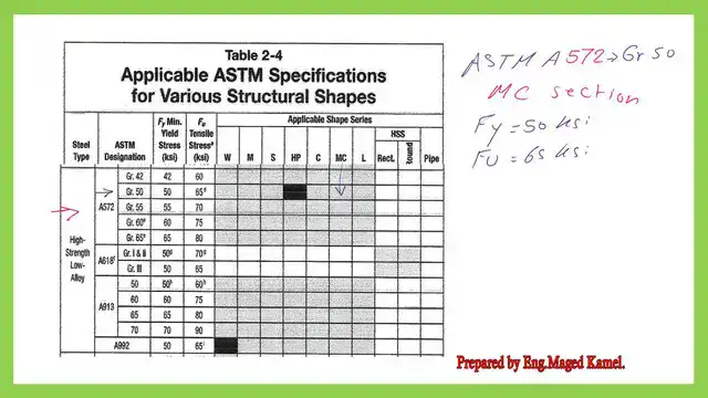
We use Tables 2-4 to obtain the yield stress and the ultimate stress (Fu) for A572 grade 50. The Fy is 50 ksi, while the Fu is 65 ksi.
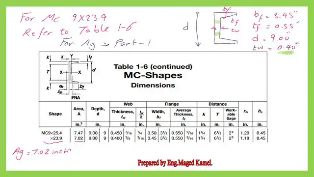
Use Table 1-6, part 1, to get the necessary information for MC 9×23.9. The area equals 7.02 inches2. The breadth of the flange is 3.45 inches, the thickness of the web is 0.40 inches, and the overall depth is 9.00 inches. Please refer to the next slide image.
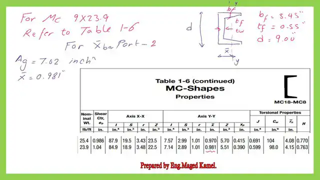
Use Table 1-6, part 2, to get the value of the x bar or the horizontal distance from Cg to the edge of the web, which equals 0.981 inches. We will use it later to evaluate the U factor.
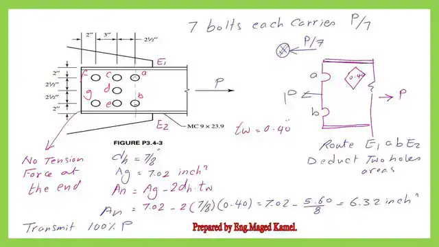
Problem 3-4-3 for staggered bolts-First route E1-A-B-E2.
We are evaluating the various options for the route of the failure line. We began investigating the first failure line, which is line E1-A-B-E2.
The route is vertical and passes by two bolts.
The net area can be estimated as the gross area minus the area of the holes. The area of the holes can be estimated as (n*db*tweb), where n=2, dh=7/8″, and the web thickness=0.4″. The final net area can be estimated at 6.32 in^2. The section is acted upon by 100% of P.
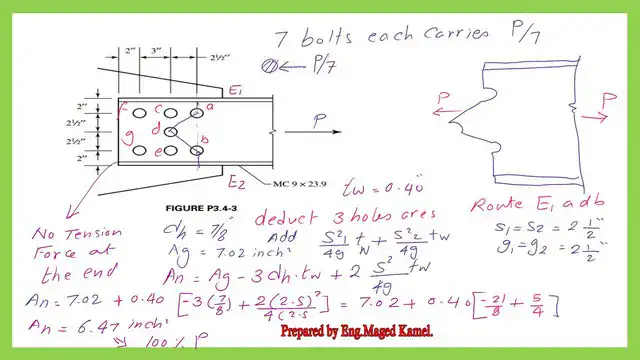
Problem 3-4-3 for staggered bolts-2nd route-E1-A-d-b-E2.
The second route, E1-A-d-b-E2, passes by three bolts with two staggered lines, ad and db.
These two lines have the same S value: the horizontal spacing between bolts in the direction of the applied force is s = 2.50 inches. The vertical distances are the same for these two lines, which are 2 1/2″.
The net area can be estimated as the gross area minus the sum of deductions and additions from staggered bolts, multiplied by the web thickness.
The hole area reduction in inches can be estimated as (n*db*tw) = 3*7/8*0.40 = 1.05 in^2. We add the sum of the tweb values (S^2/4g) for the two lines. We have equal s and g for these lines. The addition is equal to (0.4*5/4) = 0.50 in^2.
The final net area can be estimated at 6.47 in^2. The section is acted upon by 100%P. There are no bolts on the right side of the section.
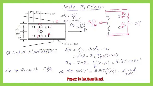
Problem 3-4-3 for staggered bolts-3rd route-E1-c-d-e-E2.
The third route, E1-c-d-e-E2, passes by three bolts; no staggered lines exist.
The net area can be estimated as equal to the gross area minus the sum of deductions.
The hole area reduction in inches can be estimated as (n*db*tw) = 3*7/8*0.40 = 1.05 in^2.
The final net area can be estimated as 5.97 inch2. 80%P acts upon the section. Two bolts are on the right side of the section.
There are 8 bolts on the left side of the section. The net area, adjusted for 100%, equals 8.358 in^2.
We come to the end of the first part; we will continue in the second part. Thank you.
The next post is problem 3-4-3 for the MC section –LRFD and ASD value-2/2.
The PDF file for this post and the next one can be viewed or downloaded from the following link.
A useful external link –Tensile yielding and tensile rupture. A Beginner’s Guide to the Steel Construction Manual, 14th ed.
A useful external link –Tensile yielding and tensile rupture. A Beginner’s Guide to the Steel Construction Manual, 15th ed.
A useful external link –Tensile yielding and tensile rupture. A Beginner’s Guide to the Steel Construction Manual, 16th ed.