Last Updated on January 8, 2026 by Maged kamel
- A solved problem 5-2 for local buckling of columns.
- Detailed data for the solved problem 5-2 for local buckling of columns.
- 1-What is the K value for the column?
- 2-Check the bf/2tf, h/tw, rx, and ry for the column.
- 3-Check whether the column is slender or not.
- 4-Using Table 4-22 for the available critical stress for compression members.
- If Using Table 4-1 for the solved problem 5-2 for local buckling.
- If Using the general provision for the available strength.
- Detailed data for the solved problem 5-2 for local buckling of columns.
A solved problem 5-2 for local buckling of columns.
This is a brief description of the content of post 12- compression.

Detailed data for the solved problem 5-2 for local buckling of columns.
A solved problem for local buckling 5-2, from Prof. Jack McCormac’s handbook.
For the column shown in Figure 5.8, if 50 ksi steel is used.
a) Using the column critical stress values in Table 4-22 of the Manual, determine the LRFD design strength Φ Pn and the ASD allowable strength P/Ωc, for the column shown in Figure 5.8.
b) Repeat the problem by using Table 4-1 of the Manual.
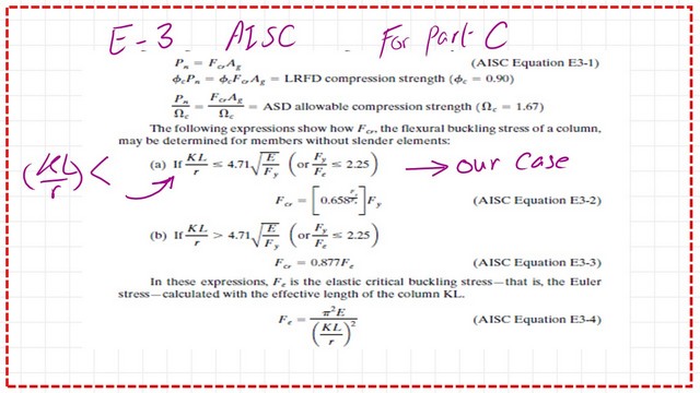
c) Solve by using the AISC equation E3.

1-What is the K value for the column?
Referring to the given section of W12x72, Height is 15 feet, fixed from the bottom and hinged from the top, kx=ky=0.7. But, the recommended values for kx and Ky are taken to be equal to 0.80.

Using Table 1-1 part 1-for the properties of the section, the flange width, bf=12 inch, the thickness of the flange is 0.67, the web thickness is equal to 0.43, and the overall height d=12.3 inch. There is no C note in the section, which means that the section is non-slender, but we will double-check the slenderness later.

2-Check the bf/2tf, h/tw, rx, and ry for the column.
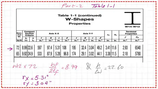
Using Table 1-1 part 2-for the properties of the section, bf/2tf=8.99, hw/tw=22.60, the radius of gyration about the x-direction, rx=5.31 inches, and the radius of gyration about the Y-direction, ry=3.04 inches.

We have to check whether the column is inelastic or elastic. We estimate the controlling lambda=4.71*sqrt(E/Fy)=4.71*sqrt(29000/50)=113.19. Estimate Kl/rx and Kl/ry and check which value is bigger, Kl/rx=27.12. At the same time, Kl/ry=47.36, the design is controlled by buckling in the Y direction, and the column is a short column.

Please refer to the slide image that shows the relation between Kl/r and the ratio of fcr/Fy. Fcr/Fy will be >0.39 but less than 1.

3-Check whether the column is slender or not.
Check the ratio b/t should be <=0.56*sqrt(E/Fy),The limiting Kl/r = 0.56 *sqrt (E/fy)=0.56 *sqrt (29000/50) = 13.48. The b/t equals 8.99. The Flange is not slender. There is another check for h/tw that should be <=1.496*sqrt(E/Fy), which is equal to 35.88.
The h/tw from the table is 22.60, which is less than 35.88; then the whole section is non-slender.

The Qs is equal to 1.0, based on CM#14 when b/t is less than 0.56*sqrt(E/Fy). Please refer to the following slide image for more details.

4-Using Table 4-22 for the available critical stress for compression members.
Refer to the table for the kl/r, and refer to the Fy=50 ksi, our kl/r about the Y-axis =47.37, this value is within the range of 47 and 48.
The Table will give Fcr corresponding to both the LRFD and ASD. For LRFD, the factored stress value is between 38.3 ksi and 38.0 ksi, by interpolation.
We will get the value of 38.189 ksi for the LRFD of the solved problem 5-2 for local buckling.
To estimate Φc* Pn=Φc*Fcr*Ag=38.189*21.10=806 kips.

While for ASD, refer to the table for the kl/r, and refer to the Fy=50 ksi, our kl/r about the Y-axis =47.37, this value is within the range of 47 and 48.
The Table will give Fcr corresponding to both the LRFD and ASD. For LRFD, the factored stress value is between 25.50 ksi and 25.30 ksi, by interpolation.
We will get the value of Pn/Ω=536.0 kips.

If Using Table 4-1 for the solved problem 5-2 for local buckling.
Then for part b, for the solved problem 5-2, using Table 4-1, as part b for the solved problem the main difference between the two tables is that table 4-1 is using the coefficient Kl, not Kl/r as used by table 4-22, previously our K*l/r=47.37, while, our kl= 0.8* 15=12 feet . From Kl=12 ft, draw a line that will intersect with a vertical line passing by W12x72.
The intersection between the two lines, will give a value of 806 kips for the LRFD design. and 536 kips for the ASD design , the same values obtained from Table 4-22 item a, these values matching each other.

If Using the general provision for the available strength.
In the third step, it is required to estimate the values by the general equation, which is part c for the solved problem 5-2, please find the relating equations for the estimate of Fcr values

For the general equation, for the short column we are dealing with the curve at the left side of the 113.43 line.The column is short, Fe=Pi^2E/(kl/r)^2=(Pi)^2(29000)/(47.37)^2, the FE value equals 127.553 ksi.

Fcr=0.658^(50/127.6557), all multiplied by(50), fcr=42.434 ksi, to be multiplied by phi=0.9 by area=21.1 inch2. We get Φ*Pn =806 kips for the LRFD.
In the case of ASD, for Ω=1.67, then Pn/Ω=42.434*(21.1)/1.67= Pn/Ω=536.14 kips, which is matching with the values obtained from Table 4-22 and Table 4-1.

The Pdf of this post can be viewed and downloaded from the next document.
The next post: solved problem 5-3 for local buckling.
This is a great external reference for limit state, here is the link: Limit State of Flexural Buckling for Slender Sections