Last Updated on February 12, 2026 by Maged kamel
- Study of Local Buckling-Part-2.
- Local Buckling-part-2-Dealing with the stiffened portion.
- Local Buckling-part-2-Dealing with the un-stiffened portion.
- Local Buckling-part-2-Modification of the equation used to estimate Fcr.
- Limiting width-to-thickness ratios for unstiffened sections.
- Limiting width-to-thickness ratios for stiffened sections.
Study of Local Buckling-Part-2.
Local Buckling-part-2-Dealing with the stiffened portion.
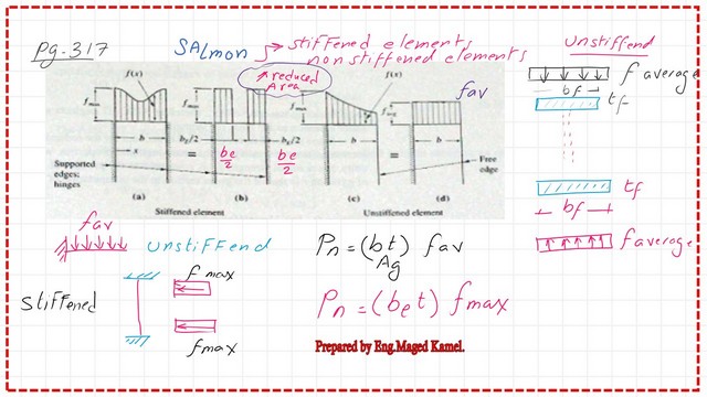
In local buckling-part-2. I Quote From Prof. Salmon’s book if we look at the stiffened plate shown, the picture which is on the left side. If we want to estimate the forces, these stresses that act is of maximum values at the edges and have a slight decrease towards the center.
If we want to estimate the average stress of-f-max, we will find can be represented by f-max with a portion of the section as if the Pn can be estimated as web thickness t to be multiplied by (be), that is the effective width, which is a part of the web, that carries the f-max multiplied by the product of (tw*be). The nominal load value Pn=tbefmax, then we can draw a new shape reduced section of the web, which we call an effective area, with height= b and width of tw acted upon by fmax .
Local Buckling-part-2-Dealing with the un-stiffened portion.
The stress distribution for the unstiffened part is shown on the right picture side.
As for the unstiffened part, we have stress f-max at the attached portion-stiffened- and stress of- f value at the free edge, then the distribution, in this case, can be considered as fav, the average stress over the entire area of the flange.
The nominal load, in this case, will be estimated as Pn of the flanges, being as unstiffened Pn (tf*bf)* fav. The product of (bf*tf) will be considered as A gr or Gross area.
While for the unstiffened equation for Pn=(fav)Agr, multiply by(fmax/f max), then take (fav/fmax) as equal to Qs. Pn can be set = Qs*fmax*Agr, but for the part of an unstiffened section.
Based on the first equation, the stiffened part, with Pn ( t*be)*fmax, or the product of effective area by maximum stress, where Aef (t*be).
We will multiply by (Agr/Agr); the equation remains valid, but again, consider Aeff/Agr = QA.
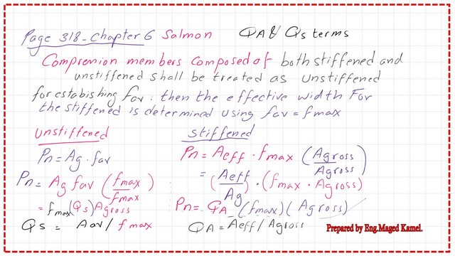
We want to estimate the Pn for the whole section. A compression member composed of both stiffened and unstiffened elements would be treated as unstiffened for establishing the stress fav.
Now consider the whole section as reduced with an effective stress of fav. Pn =fav Aeff, then multiply by (fmax/fmax), then multiply by (Ag/Ag). Using the expression of both Qa and Qs. The final expression will be Pn=Qa*Qs(f max*A gross).
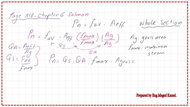
We can estimate the Qs, then work with the determined QA, and then multiply by (fmax*Agross) to estimate the Pn, but the procedure will commence after proving that the column is short.
Local Buckling-part-2-Modification of the equation used to estimate Fcr.
The formula for the critical stress for the short column will be modified, due to the case of local buckling as Fcr=QsQa(0.658 ^(Q fy/fe)Fy, the capital Q is equal to the product of (Qs*Qa).
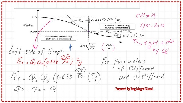
The Q factor is shown in the power for the equation, as shown in the modified equation; these were for the parameters of stiffened and unstiffened sections.
Again, we have to check whether the column is short or long by using the 4.71*sqrt(E/fy). If the column is long, we will use the equation for long columns; otherwise, we will use the equation for a short column.
Limiting width-to-thickness ratios for unstiffened sections.
Table B4.1a lists the values of width-to-thickness ratios for both unstiffened and stiffened shapes. There are four cases for the unstiffened parts; the First case is for rolled sections, with the flange coefficient bf/2tf equal to 0.56*sqrt(E/fy).
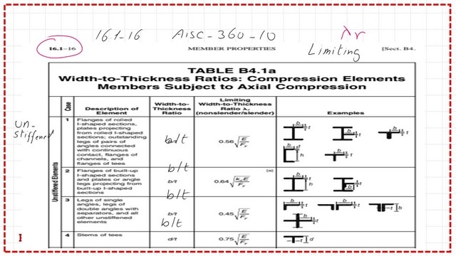
The second case is for built-up sections or portions protruding; the coefficient for the protruding portion is 0.64*sqrt(E/fy).
The third case is for the single, double, or intersection parts; the coefficient of b/t is 0.45*sqrt(E/fy).
For the T section, the fourth case, the coefficient of b/t is 0.75*sqrt(E/fy).
There are tables for both stiffened and unstiffened compression members; that is, Table B4.1A, based on AISC for unstiffened Table 1-4, Rev. B, which covers the design requirements. There are 4 cases for the unstiffened. The First case is for rolled sections.
Limiting width-to-thickness ratios for stiffened sections.
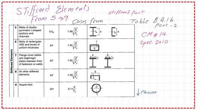
The stiffened sections are from case no. 5 to case No.9, showing the coefficients for the W section, HSS plates welded, all other stiffened elements, and round HSS.
Case 5 -h/tw is the case of doubly symmetric, the limiting width to thickness is 1.49*sqrt(E/fy)
For local buckling-part-2. While inspecting case 6, we will find that all of its parts are stiffened, as it has a stiffener.
For case no., the limiting width-to-thickness ratio is 1.40*sqrt(E/fy).
For Case no.8, all other stiffened elements, b/t the limiting width to thickness is 1.49*sqrt(E/fy).
The last case is the round HSS case, where D/t is the width-to-thickness ratio, and the limiting width-to-thickness ratio is 0.11*sqrt(E/fy).
The next post is 11- Local Buckling for stiffened and un-stiffened elements.
For an external resource, Concentrically Loaded Compression Members.